Search results for: 'Panel+c''
-
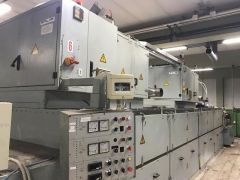
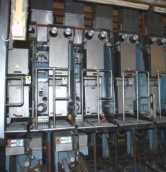 G-0784 RIETER FDY EXTRUSION EQUIPMENT FOR POLYPROPYLENE YEAR 1996/98
REFERENCE NUMBER: G-0784
RIETER FDY EXTRUSION EQUIPMENT FOR POLYPROPYLENE YEAR 1996/98
1. Machine m26/39:
Year 1996
For 1 fdy spinning line with 2+4 positions, each position with 4 ends
Product: fdy-yarn on bobbins
Raw material: pp, dried filament grade chips
Yarn count range: 150 – 400 dtex
Winder speed for target: 4000 m/min
Machine technical data:
Position gauge: 800 mm
Spinning pump capacity: 4x10 ccm/rev
Spinneret size diameter: 95 mm
Quench width: 670 mm
Quench length: 1700 mm
Number of spin-finish pumps per position: 1
Capacity of spin-finish pump: 4x0.05 ccm/rev
Number of winders/position: 1
Type of winder: riemat a6-094
Number of packages/winder: 4
Maximum package diameter: 420 mm
Package stroke: 190 mm
Package weight at 280 mm package diameter: approx. 6.2 kg
Detailed technical specifications:
Extruder for 4 positions Year 1998:
1 extruder type e1. 105-30m:
-nominal extruder capacity: max 275 kg/h for pp
-operational extruder capacity: max 248 kg/h for pp
-screw diameter: 105 mm
-l/d ratio: 30
-barrel with:
electrical ceramic heaters
7 heating zones, each zone equipped with one 2xpt100
heating zone capacity approx. 58 kw
inlet zone, water cooled
nozzle for nitrogen purge
insulation
-screw with torpedo mixing head
-reduction gear, including belt transmission to motor
-dc motor, rated power approx. 95kw
-extruder frame
1 extruder measuring head, dowtherm vapour heated
-measuring head comprising:
coarse filter
insulation
-double pt100, one each for melt and dowtherm vapour temperature
-pressure sensors for melt pressure, one in front and one behind the coarse filter
1 melt distribution system, dowtherm vapour heated
-melt distribution system comprising
main product pipe between extruder, measuring head and melt distributor.
Extruder for 2 positions Year 1998:
1 extruder type e1. 60-30
-nominal extruder capacity: max 275 kg/h for pp
-operational extruder capacity: max 248 kg/h for pp
-screw diameter: 60 mm
-l/d ratio: 30
-barrel with
electrical ceramic heaters
6 heating zones, each zone equipped with one 2xpt100
heating zone capacity approx. 17 kw
inlet zone, water cooled
insulation
-screw nitrited with maddock mixing head
-reduction gear, including belt transmission to motor
-dc motor, rated power approx. 22kw
-extruder frame
1 extruder measuring head, electrically heated year 1998
-measuring head comprising:
insulation
Double pt100, one each for melt and dowtherm vapour temperature
pressure sensors for melt pressure
burst disc for power switch-off at overpressure.
1 melt distribution system, dowtherm vapour heated
-melt distribution system comprising
main product pipe between extruder, measuring head and melt distributor.
1 riebeam bottom loading spinning beam year 1998
-beam comprising:
welded-in pump blocks with bolted pump adapter plate
silumin insulation blocks
melt distribution pipes with polished inner surfaces
efficient vapour heating on all sides of spin pumps
optimized heat condustion to the spinnerets
1 freezing valve upstream of each spinpump
2 pressure sensors for measuring the melt pressure in front and behind the spinpump
(2 per line)
heating box, completely insulated
heating by dowtherm vapour
1 double pt100 for measuring and controlling the heating box temperature
Designed as follows:
-bottom loading of rieter quickfit spinpacks
-design temperature 320°c
-maximum allowable working pressure: 300 bar for melt pipe and 2.57 bar for jacket
Dowtherm evaporator and components for heating system:
-electrically heated, total capacity approx 25 kw
-shut-off valves
-drainage valves
-dry protection sensor
-magnetic controlled level gauge
- vent system on top of measuring head.
Poy spin packs, type rieter quickfit:
-max pressure in the spinpack: 350 bar
-design temperature: 320 °c
-spinneret outside dimensions: 95 mm
-bottom loading design
-bayonet locking, insert and tighten by turning 90°
-self sealing system
-sand or metal powder filtration, 3 cm filling depth
-wire mesh filters
Spin pumps with motors and gears:
Gear pumps, 4-fold
Capacity 4 x 6 ccm/rev
Each spin pump system comprising
Individual drive motor with flange connection to the reduction gear
Hollow gear shaft for installation of spin pump shaft
Shaft with shear pin protection
Reduction ratio 1:80
Pump speed: 8-30 rev/min
Motor type: synchronous ac-motor
Rated power: 500w at 50 cps
Quench air cabinets bsk 670/1700:
Each cabinet comprising:
-rigid cabinet made from welded sheet metal, painted, side walls made from alu sheet metal
-air rectifier consisting of different layers of perforated metal sheets, rectifiers removable to the front for cleaning.
-1 perforated hinged door
-air inlet duct flanged with counter flange, comprising air flow regulating flaps
-interfloor filament duct, length 2000 mm
-alu chutes for start-up
-nozzles for connection of differential pressure gauge.
Spinning vapour exhausts:
-exhaust hood per spinning position for removal of spinning vapour
-hood designed as follows:
made from stainless steel
air flow regulation flap
hood removable for cleaning
Take-up frames, type riedraw 1:
Welded steel frame, housing all drawrolls, compressed air supply pipes for the aspirator units and the yarn waste pipes within the fdy take-up unit.
Per position:
4 inlet yarn guides
4 spin finish application nozzles
1 yarn cutter / aspirator unit
1 spin finish pump
4 centring yarn guides
4 intermingling units
rolls as described further
1 automatic winder riemat a6-094
Drawrolls year 1998:
Mono 1 with 1 rievap 32 dual shell drawroll, type j7/32-40, ot40
Speed range: 750 to 4000 mpm
Roll diameter: 190 mm
Working width: 250 mm
Temperature range: 45-250°c
And 1 bearing separator roll, type srd60 hard chromium plated
Duo 1 with 2 rievap 32 dual shell drawroll, type j7/32-60, ot40
Speedrange: 1000 to 6000 mpm
Roll diameter: 190 mm
Working width: 250 mm
Temperature range: 45-250°c
Duo 2 with 2 rievap 32 dual shell drawroll, type j7/32-60, ot40
Speedrange: 1000 to 6000 mpm
Roll diameter: 190 mm
Working width: 250 mm
Temperature range: 45-250°c
Duo 3 with 2 cold draw roll units each type j7/45-55
Speedrange: 1800 to 5500 mpm
Roll diameter: 150 mm
Working width: 180 mm
Automatic and wasteless winder riemat a6-094
Spindle driven
Number of ends per winder: 4 ends
Yarn count range: 15 to 1000 dtex
Take up speed: 2500 to 5500 m/min
Chuck length: 900 mm
190 mm stroke, 420 mm outside package diameter
Package volume: 24.7 dm³
Tube bore: 94 ±0.2 mm
Tube outside diameter: 106 ±0.4 mm
Tube length: 225 ±0.5 mm
Oil-mist lubrication unit:
Compressed air distribution station
Mobile aspirator guns with hoses
Electrical control equipment
-for electrical power
general: 3 x 380v/50hz plus ground wire
euro-standard: 3x400v 50 or 60hz plus ground wire
maximum voltage variation ±10% measured at terminals of cabinets
maximum frequency variation: ±2%
Process control system (cif):
fully integrated control system to control and monitor the entire spinning line.
the central monitoring unit si linked to the plc of the spinning section and the plcs of each spinning position.
Drive and heater control year 1998:
Spinning section:
Speed adjustment for the extruder motor is done via a dc-convertor
To achieve a constant pressure at the extruder outlet, the output of the pressure controller is transmitted to the dc-converter to adjust the extruder speed.
The feedback of the actual extruder speed is done by a tacho generator mounted on the extruder motor.
One common frequency inverter supplies the synchronous ac motors for the spin pumps.
According to process conditions, the plc transmits the setpoint to the inverter.
All motors are equipped with an overload protection.
Solid state relays heat each extruder zone and spinning beam.
Each extruder zone and the spinning beam represent an independent control loop.
Take-up section:
The inverter unit is a processor-controlled static frequency inverter for powering the 3-phase motors.
All inverter units in a position cabinet are supplied with approx 570v dc from a common rectifier.
Heating system:
The heating unit rhu is processor-controlled.
The power supply is taken straight from 3-phase 380/400v which powers the cabinet.
The inductor is fitted inside the draw roll.
The rhu switches the current on and off in this inductor. While current flows, a voltage is inducted into the
Rotating draw roll.
This sets up a short-circuit current in the draw roll, thereby heating the roll unit.
2. Machines m27/ 28 / 30 year 1998:
For 3 fdy spinning lines each with 2 positions, and each position with 4 ends
Product: fdy-yarn on bobbins
Raw material: pp, dried filament grade chips
Yarn count range: 150 – 400 dtex
Winder speed for target: 4000 m/min
Machine technical data:
Position gauge: 1000 mm
Spinning pump capacity: 4x7.5 ccm/rev
Spinneret size diameter: 95 mm
Quench width: 470 mm
Quench length: 1200 mm
Number of spin-finish pumps per position: 2
Capacity of spin-finish pump: 4x0.16 ccm/rev + 4x0,05 ccm/rev
Number of winders/position: 1
Type of winder: riemat a6-094
Number of packages/winder: 4
Maximum package diameter: 420 mm
Package stroke: 190 mm
Package weight at 280 mm package diameter: approx. 6.2 kg
Detailed technical specifications:
1 extruder type e1. 60-30m
-nominal extruder capacity: max 80 kg/h for pp
-screw diameter: 65 mm
-l/d ratio: 30
-barrel with:
electrical ceramic heaters
7 heating zones, each zone equipped with one 2xpt100
heating zone capacity approx. 22 kw
inlet zone, water cooled
nozzle for nitrogen purge
insulation
-screw with torpedo mixing head
-reduction gear, including belt transmission to motor
-dc motor, rated power approx. 22kw
-extruder frame
1 extruder measuring head, electrically heated:
-measuring head comprising:
coarse filter
insulation
-double pt100, one each for melt and dowtherm vapour temperature
-pressure sensors for melt pressure, one in front and one behind the coarse filter
1 melt distribution system, dowtherm vapour heated:
Melt distribution system comprising:
main product pipe between extruder, measuring head and melt distributor.
1 riebeam bottom loading spinning beam:
-beam comprising:
welded-in pump blocks with bolted pump adapter plate
silumin insulation blocks
melt distribution pipes with polished inner surfaces
efficient vapour heating on all sides of spin pumps
optimized heat condustion to the spinnerets
1 freezing valve upstream of each spinpump
2 pressure sensors for measuring the melt pressure in front and behind the spinpump
(2 per line)
heating box, completely insulated
heating by dowtherm vapour
1 double pt100 for measuring and controlling the heating box temperature
Designed as follows:
-bottom loading of rieter quickfit spinpacks
-design temperature 320°c
-maximum allowable working pressure: 300 bar for melt pipe and 2.57 bar for jacket
Dowtherm evaporator and components for heating system:
-electrically heated, total capacity approx 18 kw
-shut-off valves
-drainage valves
-dry protection sensor
-magnetic controlled
-level gauge
-vent system on top of measuring head.
Poy spin packs, type rieter quickfit:
Max pressure in the spinpack: 350 bar
Design temperature: 320 °c
Spinneret outside dimensions: 95 mm
Bottom loading design
Bayonet locking, insert and tighten by turning 90°
Self sealing system
Sand or metal powder filtration, 3 cm filling depth
Wire mesh filters
Spin pumps with motors and gears:
Gear pumps, 4-fold
Capacity 4 x 7.5 ccm/rev
Each spin pump system comprising
individual drive motor with flange connection to the reduction gear
hollow gear shaft for installation of spin pump shaft
shaft with shear pin protection
reduction ratio: 1:80
pump speed: 8-30 rev/min
motor type: synchronous ac-motor
rated power: 500w at 50 cps
Quench air cabinets bsk 470/1200
Each cabinet comprising:
-rigid cabinet made from welded sheet metal, painted, side walls made from alu sheet metal
-air rectifier consisting of different layers of perforated metal sheets, rectifiers removable to the front for cleaning.
-1 perforated hinged door
-air inlet duct flanged with counter flange, comprising air flow regulating flaps
-interfloor filament duct, length 2000 mm
-alu chutes for start-up
-nozzles for connection of differential pressure gauge.
Spinning vapour exhausts:
-exhaust hood per spinning position for removal of spinning vapour
-hood designed as follows:
made from stainless steel
air flow regulation flap
hood removable for cleaning
Take-up frames, type riedraw 1:
Welded steel frame, housing all drawrolls, compressed air supply pipes for the aspirator units and the yarn waste pipes within the fdy take-up unit.
Per position:
4 inlet yarn guides
2 spin finish application nozzles per end
1 yarn cutter / aspirator unit
2 spin finish pump
4 centring yarn guides
4 pre-intermingling jets
4 intermingling units
1 additional operator panel between duo1 and duo 2.
rolls as described further
1 automatic winder riemat a6-094
Drawrolls:
Mono 1 with 1 rievap 32 dual shell drawroll, type j7/32-40, ot40
Speedrange: 750 to 4000 mpm
Roll diameter: 190 mm
Working width: 250 mm
Temperature range: 45-250°c
And 1 bearing separator roll, type srd60
Hard chromium plated
Duo 1 with 2 rievap 32 dual shell drawroll, type j7/32-60, ot40
Speedrange: 1000 to 6000 mpm
Roll diameter: 190 mm
Working width: 250 mm
Temperature range: 45-250°c
Duo 2 with 2 rievap 32 dual shell drawroll, type j7/32-60, ot40
Speedrange: 1000 to 6000 mpm
Roll diameter: 190 mm
Working width: 250 mm
Temperature range: 45-250°c
Duo 3 with 2 cold draw roll units each type j7/45-55
Speedrange: 1800 to 5500 mpm
Roll diameter: 150 mm
Working width: 180 mm
Automatic and wasteless winder riemat a6-094:
Spindle driven
Number of ends per winder: 4 ends
Yarn count range: 15 to 1000 dtex
Take up speed: 2500 to 5500 m/min
Chuck length: 900 mm
190 mm stroke, 420 mm outside package diameter
Package volume: 24.7 dm³
Tube bore: 94 ± 0.2 mm
Tube outside diameter: 106 ± 0.4 mm
Tube length: 225 ± 0.5 mm
Compressed air distribution station:
Mobile aspirator guns with hoses
Electrical control equipment
For electrical power
general : 3 x 380v/50hz plus ground wire
Euro-standard: 3x400v 50 or 60hz plus ground wire
Maximum voltage variation ±10% measured at terminals of cabinets
maximum frequency variation: ±2%
Process control system (cif):
Fully integrated control system to control and monitor the entire spinning line.
The central monitoring unit si linked to the plc of the spinning section and the plcs of each spinning position.
Drive and heater control:
Spinning section.
Speed adjustment for the extruder motor is done via a dc-convertor.
To achieve a constant pressure at the extruder outlet, the output of the pressure controller is transmitted to the dc-converter to adjust the extruder speed.
The feedback of the actual extruder speed is done by a tacho generator mounted on the extruder motor.
One common frequency inverter supplies the synchronous ac motors for the spin pumps.
According to process conditions, the plc transmits the setpoint to the inverter.
All motors are equipped with an overload protection.
Solid state relays heat each extruder zone and spinning beam.
Each extruder zone and the spinning beam represent an independent control loop.
Take-up section:
The inverter unit is a processor-controlled static frequency inverter for powering the 3-phase motors.
All inverter units in a position cabinet are supplied with approx 570v dc from a common rectifier.
Heating system:
The heating unit rhu is processor-controlled.
The power supply is taken straight from 3-phase 380/400v which powers the cabinet.
The inductor is fitted inside the draw roll.
The rhu switches the current on and off in this inductor.
While current flows, a voltage is inducted into the rotating draw roll.
This sets up a short-circuit current in the draw roll, thereby heating the roll unit.
HOURLY PRODUCTION:
FOR 150 DENIER @ 3500 MPM WINDER SPEED, THE HOURLY PRODUCTION IS 3.5 KG/BOBBIN.
AS THERE IS 4 ENDS PER POSITION, THIS MEANS 14 KG/HOUR/POSITION
M26/39 ARE OF 2 + 4 POSITIONS; HENCE M26 = 28 KG/HOUR AND M39 = 56 KG/HOUR
M27/28/30 ARE OF 2 POSITIONS EACH, HENCE 28 KG/HOUR EACH.
(AS PER OUR PEOPLE AT THE EXTRUSION PLANT, THEY WERE RUNNING TRIALS TO PRODUCE THE 150 DENIER @ 4000 MPM WINDER SPEED)
FOR 300 DENIER @ 3600 MPM WINDER SPEED, THE HOURLY PRODUCTION IS 7.2 KG/BOBBIN.
AS THERE IS 4 ENDS PER POSITION, THIS MEANS 28.8 KG/HOUR/POSITION
M26/39 ARE OF 2 + 4 POSITIONS; HENCE M26 = 57.6 KG/HOUR AND M39 = 115.2 KG/HOUR
M27/28/30 ARE OF 2 POSITIONS EACH, HENCE 57.6 KG/HOUR EACH.
FOR 600 DENIER @ 2200 MPM WINDER SPEED, (SPEED LIMITATION DUE TO EXTRUDER CAPACITY) THE HOURLY PRODUCTION IS 8.8 KG/BOBBIN.
AS THERE IS 4 ENDS PER POSITION, THIS MEANS 35.2 KG/HOUR/POSITION
M26/39 ARE OF 2 + 4 POSITIONS; HENCE M26 = 70.4 KG/HOUR AND M39 = 140.8 KG/HOUR
M27/28/30 ARE OF 2 POSITIONS EACH, HENCE 70.4 KG/HOUR EACH.
MACHINE HAS BEEN PARTIALLY DISASSEMBLED (EXTRUDERS AND SPINBEAMS HAVE BEEN TAKEN DOWN TO GROUNDFLOOR) REST OF THE EQUIPMENT STILL TO BE DISASSEMBLED
Learn More -
 M-3984 RING SPINNING
REFERENCE NUMBER: M-3984
RING SPINNING
(1) TRUTZSCHLER BLENDOMAT BDT 019, YEAR 1990
(1) TRUTZSCHLER BLENDER GBRA 1000, YEAR 1990
(1) TRUTZSCHLER AXIFLOW AFC, YEAR 1990
(1) TRUTZSCHLER MULTIMIXER MPM8/1400, YEAR 1990
(1) TRUTZSCHLER SEPAROMAT ASTA 800, YEAR 1990
(2) TRUTZSCHLER SILO BEB 1200, YEAR 1990
(2) TRUTZSCHLER FIBER OPENER RST, YEAR 1990
(5) TRUTZSCHLER CONDENSER LVSA, YEAR 1990
(4) TRUTZSCHLER FAN TV 425, YEAR 1990
(2) TRUTZSCHLER FAN TVF 425, YEAR 1990
(3) TRUTZSCHLER FAN TV 500, YEAR 1990
(1) TRUTZSCHLER FAN TVK 650, YEAR 1990
(3) TRUTZSCHLER FILTER SFV 123, YEAR 1990
(1) TRUTZSCHLER FILTER SFF 3, YEAR 1990
(3) TRUTZSCHLER CYCLON ANB AT, YEAR 1990
(1) TRUTZSCHLER FEED TABLE (OPENING) M30 S/C, YEAR 1990
(2) TRUTZSCHLER FEED TABLE (FILTER) S/N S/C, YEAR 1990
(1) TRUTZSCHLER FEED TABLE (CARDS), YEAR 1990
(14) TRUTZSCHLER CHUTE FEED FBK 533, YEAR 1990
(5) RIETER DRAW FRAME SB2, CAN SIZE 1000x1200mm, YEAR 1997
(2) RIETER DRAW FRAME RSB D30, CAN SIZE 500x1000mm, YEAR 1999
(3) RIETER DRAW FRAME RSB 951, CAN SIZE 600x1200mm, YEAR 1997
(2) ZINSER/HARA LAP FORMER 820, 20 POSITIONS, 1000x1040mm, YEAR 1990
(12) ZINSER/HARA COMBER 830, CAN SIZE 500x1200mm, YEAR 1990
(1) ELECTRONIC CLEANER PANEL, YEAR 1990
(5) ZINSER ROVING FRAME 660, 120 POSITIONS, 16x6, CAN SIZE 500x1000mm, YEAR 1990.
(3) SOHLER AIRTEX OVERHEAD BLOWER SP 88 ZB, YEAR 1990
(20) ZINSER RING FRAME 321E, 1000 SPINDLES, RING DIA 45mm, GAUGE 75mm, YEAR 1990
(10) SOHLER AIRTEX OVERHEAD BLOWER AP 88 ZZ WI, YEAR 1990
(1) SUCTION FAN, YEAR 1990
(4) MURATA WINDER 7 II (MACH CONER), 60 POSITIONS, WITH LUWA OVERHEAD BLOWER, YEAR 1990
(1) XORELLA STEAMER CONTEXXOR, YEAR 1990
Learn More -
T-6550 MEDICAL PROTECTIVE CLOTHING BLOOD SYNTHETIC PENETRABILITY TESTER
REFERENCE NUMBER: T-6550
MEDICAL PROTECTIVE CLOTHING BLOOD SYNTHETIC PENETRABILITY TESTER
TECHNICAL SPECIFICATIONS AND CONFIGURATION:
1. THE INSTRUMENT ADOPTS AN AIR SOURCE THAT CAN PROVIDE (0.5 ~ 30±0.1) KPA PRESSURE TO CONTINUOUSLY PRESSURIZED THE SAMPLE, WHICH IS NOT RESTRICTED BY THE SPACE OF THE TEST SITE;
2. THE AIR PRESSURE RANGE CAN BE ADJUSTED FREELY, AND THE ADJUSTMENT RANGE (0.5 ~ 30) KPA;
3. COLOR TOUCH SCREEN DISPLAY AND OPERATION;
4. THE SAMPLE CLAMPING PAD IS PROCESSED WITH IMPORTED SPECIAL ALUMINUM PROFILES, WHICH IS LIGHT IN MATERIAL, CLEAN IN SURFACE AND NEVER RUSTS.
5. THE INSTRUMENT ADOPTS IMPORTED SPECIAL ALUMINUM WIRE DRAWING PANEL, EQUIPPED WITH METAL KEYS, SENSITIVE OPERATION, NOT EASY TO DAMAGE;
6. CLAMPING DEVICE FOR INSTRUMENT SAMPLES, EQUIPPED WITH LOCKING PROTECTION, TO PREVENT THE SYNTHETIC BLOOD FROM SPLASHING AROUND;
7. CLAMPING FORCE IS ACCURATE AND RELIABLE;
8. THE TEST TANK IS EQUIPPED WITH A SPECIAL PLACEMENT DEVICE, WHICH IS CONVENIENT FOR CUSTOMERS TO OPERATE;
9. THE TEST TANK IS PROCESSED WITH SPECIAL 316 STAINLESS STEEL, AND THE TOP IS EQUIPPED WITH A SPECIAL COVER FOR HIGH TRANSPARENT PROTECTION;
10. THE WASHER BELOW THE SAMPLE IS MADE OF HIGH-QUALITY PTFE MATERIAL AFTER SPECIAL PROCESSING;
11. SQUARE METAL BLOCK NET: OPEN SPACE ≥50°%; BENDING ≤5mm AT 30KPA;
12. INSTRUMENT TIME CONTROL ACCURACY ≤01 SECONDS;
13. THE SHELL OF THE INSTRUMENT IS MADE OF HIGH-QUALITY METAL BAKING PAINT, WHICH IS BEAUTIFUL AND GENEROUS.
14. EQUIPPED WITH PRINTER INTERFACE, CONNECTED TO THE PRINTER CAN DIRECTLY PRINT DATA REPORTS.
TECHNICAL PARAMETERS:
1. SAMPLE SIZE: 75mm X 75mm
2. TEST AREA: 28.26 SQUARE CENTIMETERS
3. AIR PRESSURE ADJUSTMENT RANGE (0.5 ~ 30) KPA
4. EXTERNAL SIZE: 500mm X 500mm X 500mm (L X W X H)
5. WEIGHT OF THE INSTRUMENT: 40 KG
6. POWER SUPPLY: AC220V, 50HZ,SCOPE OF SUPPLY: 1. ONE MAIN MACHINE; 2. TWO PTFE GASKETS; 3. TWO ORDINARY WASHERS; 4. ONE METAL BLOCKING NET; 5. A SET OF SPECIAL LOCKING TOOLS; 6. ONE HIGH-QUALITY SILENT AIR PUMP, [NOTE: SAFETY PRODUCTION LICENSE IS NOT INCLUDED]. 7. EQUIPPED WITH PRINTER INTERFACE; 8. ONE SAMPLE TEMPLATE; 9. ONE PRODUCT CERTIFICATE; 10. ONE COPY OF PRODUCT OPERATION MANUAL.
OPERATION INSTRUCTION:
INSERT THE AIR PUMP OUTPUT PIPE INTO THE OIL AND WATER SEPARATOR OF THE INSTRUMENT AS REQUIRED (PRESSURE 0.1-0.3MPA).
AFTER SWITCHING ON THE POWER, THE STARTUP INTERFACE (NAME OF THE DEVICE) IS DISPLAYED.
PRESS THE "ENTER" BUTTON TO ENTER THE TEST INTERFACE, AS SHOWN IN THE FOLLOWING FIGURE:
CLICK "SETTING” BUTTON, GET INTO PARAMETER SETTING SCREEN, AS BELOW THIS SCREEN CAN SET THE SYSTEM TIME, DATE AND TESTING TIME, AFTER SETTING, CLICK "SAVE” BUTTON TO KEEP THE SETTING DATA. (NOTE: IT REQUIRES 5 MINUTES IN THE STANDARD)
QUANTITY: 1
Learn More -
 R-7504 LLOVERAS CHOCOLATE MOULDING LINE MOULD SIZES OF 400 X 200 X 30mm HIGH
REFERENCE NUMBER: R-7504
Learn More
LLOVERAS CHOCOLATE MOULDING LINE
MANUFACTURED BY LLOVERAS
MODEL SIMA N400/1M
MOULD SIZES OF 400 X 200 X 30mm HIGH
QUANTITY: 1 -
K-8416 G1 TONELLO 330 "CENTRIFUGING" INDUSTRIAL WASHING MACHINE-USED
REFERENCE NUMBER: K-8416
G1 TONELLO 330 "CENTRIFUGING" INDUSTRIAL WASHING MACHINE-USED
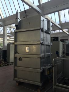
G1 TONELLO 330
“CENTRIFUGING” INDUSTRIAL WASHING MACHINE
FRONTAL TYPE
FOR CHEMICAL “STONE WASH”
CAPACITY LIT. 3.300
MOD. TONELLO G1 330
GENERAL DESCRIPTION:
TONELLO G1 IS A MACHINE WITH HIGH-SPEED HYDRO-EXTRACTION (600 R.P.M.) AND IT IS EQUIPPED WITH AUTOMATIC SELF-BALANCING SYSTEM
TONELLO G1 IS SUPPLIED WITH “SETTABLE INVERTER”
ROTATION SPEED FROM 0 TO 55 R.P.M
ALSO SETTING THE CENTRIFUGING SPEED FROM 0 TO 600 R.P.M.
WITH TIME OF CENTRIFUGE PROGRAMMABLE BY INDUSTRIAL PC
THE ACCESS MAIN DOOR TO THE DRUM IS VERY WIDE, IN ORDER TO EASY GARMENTS LOADING AND UNLOADING OPERATION
OPENING AND CLOSING ARE PNEUMATIC
DOUBLE TILTING SYSTEM FOR GARMENTS LOADING AND UNLOADING
DRIVING SYSTEM IS SITUATED ON THE UPPER PART OF THE MACHINE
WITH PROPER MATERIAL AND MOTORS SUITABLE TO WORK AT LOW AND HIGH R.P.M.
1 TANK FOR THE PREPARATION OF AUXILIARY PRODUCTS WITH CAPACITY OF LITTERS 180 EQUIPPED WITH ELECTRO-PUMP AND PNEUMATIC VALVES FOR THE SENT ONE
THE DRAINAGE IN DRAIN AND AUTOMATIC RINSES N° 2 WATER INLETS COMPLETE WITH PNEUMATIC VALVE- MECHANICAL WATER-COUNTER DIRECT HEATING AND COOLING SYSTEM
AUTOMATION WITH MICROPROCESSOR
TECHNICAL DATA TONELLO G1 330
DRUM DIMESION
-DRUM HOLING SHEET mm 4
THICKNESS
-DIAMETER MM 1900
-DEPTH MM 1150
-VOLUME LT. 3300
-DOOR DIAMETER MM 1020
-MAXIMUM LOADING KG. 120/130
CAPACITY
BASKET SPIN SPEED RPM 0-600
DIRECT STEAM CONNECTION Ø 1" 1/4
WATER INLET CONNECTION Ø 2 x 2
COMPRESSED AIR INLET Ø 1/4"
CONNECTION
STEAM IN MAXIMUM PRESSUREBAR BAR 6
WATER IN MAXIMUM PRESSURE BAR 4
COMPRESSED AIR IN MAXIMUM BAR 8
PRESSURE
POWER INSTALLED KW 22
3-PHASE VOLTAGE VOLT/HZ 400/50
PRODUCTS TANK Ø 240 H 400 LT. 80
TANK RINSING VALVE Ø 1/2"
MACHINE SIZE
-WIDTH MM 2500
-WIDTH WITH ELECTRICAL PANEL MM 2980
-DEPTH MM 2710
-HEIGHT MM 3000
Learn More -
C-4020 BENNINGER SIZING AND WARPING MACHINES, WORKING WIDTH 2200mm TO 4000mm, YEAR 1996 TO 1997
C-4020 BENNINGER SIZING AND WARPING MACHINES, WORKING WIDTH 2200mm TO 4000mm, YEAR 1996 TO 1997
OFFER 001
BENNINGER SIZING MACHINE
YEAR: 1996 TO 1997
HEAD BEAMS WIDTH: 4000mm
BEAM DIAMETER: 1000mmQUANTITY: 2
OFFER 002
BENINGER DIRECT WARPERS
YEAR: 1996 TO 1997
WORKING WIDTH: 2200mm
DIAMETER: 1000mmQUANTITY: 2
OFFER 003
BENINGER SECTIONAL WARPER
WORKING WIDTH: 4000mm
DIAMETER: 1000mmQUANTITY: 1
Learn More -
J-0071 WEISS TUBULAR COMPACTOR WIDTH 1524mm YEAR 1996REFERENCE NUMBER: J-0071 (220NGMFXX1) J WEISS TUBULAR COMPACTOR WIDTH WIDTH 1524mm YEAR 1996 TUBULAR COMPACTOR WIDTH: 1524mm YEAR: 1996 QUANTITY AVAILABLE: 1 Learn More
-
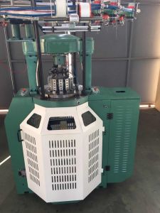 H-2413 RIB CIRCULAR KNITTING MACHINE 5”
CYLINDER DIAMETER: 5”
NO. OF FEEDERS: 10
130 NEEDLESGOLDEN ROC NEEDLE
DIAL 43.50 NEEDLE 2 TYPES
CYLINDER 122.48
NEEDLE 2 TYPES
NEEDLE DETECTOR: 6 PCS
DIGITAL CONTROL PANEL
CAM: 1 SET (MADE OF ALLOY STEEL, JAPAN)
CYLINDER 2 TRACKS, DIAL 2 TRACKS
TOTAL CAMS: 40 PCS
PNEUMATIC OIL LUBRICATOR
SMG POSITIVE STORAGE FEEDER
YARN FEEDING TOOTHED BELT
CYLINDER (MADE OF ALLOY STEEL, JAPAN)
INVERTER
LYCRA FEEDER
MOTOR
CREEL HOLDERS
FABRIC ROLLING MACHINESPARE PARTS:
CAM × 1 PC/TYPE
TOOLBOX (WITH TOOLS INSIDE) × 1 PC
NEEDLE DETECTOR × 2 PCS
NEEDLE × 100 PCS
YARN CARRIER × 2 PCS
POSITIVE STORAGE FEEDER × 2 PCSSHIPPING DIMENSIONS (WOODEN CASE): LENGTH 1600mm, WIDTH 1100mm, HEIGHT 2200mm 3.87 CBM
GROSS WEIGHT: 550 KGSQUANTITY: 1
Learn More -
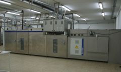
 J-1375 STALAM HIGH FREQUENCY DRYER, YEAR 2001, 50+50kW
J-1375 STALAM HIGH FREQUENCY DRYER, YEAR 2001, 50+50kW
MAKE: STALAM
MODEL: LTRF – RFA-S
YEAR: 2001
RF POWER OUTPUT: 50+50kW
EQUIPPED WITH:
-LOADING STATION 2150mm with POLYESTER BELT WIDTH 2000mm
-1 DRYING SECTION OF 50kW: 4000mm
-1 DRYING SECTION OF 50kW: 4000mm
-UNLOADING STATION 2000mm
OVERALL DIMENSIONS : 12150mm LONG x 2500m WIDE X 3200mm TALL
(THE LEGS CAN BE REMOVED SO THAT THE SHIPPING HEIGHT CAN BE REDUCED TO 2400mm HIGH FOR 40’ HIGH CUBE SHIPPING CONTAINER)
EQUIPPED WITH CONTROL PANELQUANTITY: 1
Learn More -
 T-1138 LORIS BELLINI APPC/LV 150 HANKS CABINET DYEING MACHINE, YEAR 1988 RECONDITIONED 2016
REFERENCE NUMBER: T-1138
LORIS BELLINI APPC/LV 150 HANKS CABINET DYEING MACHINE, YEAR 1988 RECONDITIONED 2016
HANKS CABINET DYEING MACHINE
UNDER PRESSURE TEMPERATURE 110°C
WITH EXTRACTABLES BASKETS
MODEL LORIS BELLINI APPC/LV 150
YEAR 1988 FULLY RECONDITIONED 2016
QUANTITY: 1
Learn More