Search results for: '2500'
- Related search terms
- 2500 kw natural gas generator
- 2500 mm lo
- 2500 mm looms
- 2500/1500
- 2500*4
-
 M-6055 NONWOVEN NEEDLE FELT LINE, WIDTH 4300mm, YEAR 1970 TO 2004
M-6055 NONWOVEN NEEDLE FELT LINE, WIDTH 4300mm, YEAR 1970 TO 2004
OFFER 001
NONWOVEN NEEDLE FELT LINE – RENEWED 3 YEARS AGO
WORKING WIDTH: 4300mmOFFER 002
HERGETH BALE OPENER
YEAR: 1986
WORKING WIDTH: 1000mmOFFER 003
OILING UNIT
TANK CAPACITY: 250 LITRESOFFER 004
AUGUST PROTT FAN FOR FIBER TRANSPORT
POWER: 7.5 KWOFFER 005
TERMO GORING KERR METAL DETECTOR AND METAL SEPARATOR
YEAR: 2004OFFER 006
TEMAFA MIXING BINOFFER 007
FOR FAN FOR FIBER TRANSPORTATIONOFFER 008
FOR CHUTE FEED WITH MOVEABLE CONDENSOR
WORKING WIDTH: 2500mmOFFER 009
WEB DENSITY MEASURING AND AUTOMATIC ALIGNINGOFFER 010
FOR CARDING MACHINE
WORKING WIDTH: 2500mmOFFER 011
ASSELIN CROSSLAPPER
YEAR: 1984
INPUT WIDTH: 2500mmOFFER 012
FEHRER FIRST NEEDLE LOOM
YEAR: 1973
WORKING WIDTH: 4800mmOFFER 013
UNWINDING FOR PRELIMINARY WEBOFFER 014
CONVEYOR SYSTEM FOR WEB TRANSPORTATION TO SECOND NEEDLE LOOMOFFER 015
FEHRER SECOND NEEDLE LOOM
YEAR: 1970
WORKING WIDTH: 4400mmOFFER 016
FEHRER THIRD NEEDLE LOOM
YEAR: 1973
WORKING WIDTH: 4800mmOFFER 017
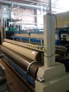
BENEDETTI & CALAMAI TRIMMING AND WINDING UNIT
YEAR: 1995
TABLE WIDTH: 5500mmOFFER 018
LAROCHE EDGE TRIM OPENERQUANTITY: 1 LINE
Learn More -
 V-1177 GEOTEXTIL NEEDLE PUNCH PRODUCTION LINE, FINAL FABRIC WIDTH 6000mm
V-1177 GEOTEXTIL NEEDLE PUNCH PRODUCTION LINE, WORKING WIDTH 2500mm TO 7400mm, YEAR 1992 TO 1994
OFFER 001
PRODUCTION SPEED: 20 M/MIN
WEIGHT: 130 TO 600 G/M²COMPOSED OF:
OFFER 002
HERGETH CARDINGOFFER 003
ASSELIN CROSSLAPPEROFFER 004
FEHRER PRE-NEEDLINGOFFER 005
FEHRER NEEDLINGOFFER 006
ACCUMULATORQUANTITY: 1 LINE
Learn More -
 ASSELIN, HERGETH, SPINNBAU, TRUTZSCHLER COMPLETE NONWOVEN LINEREFERENCE NUMBER: T-6841 ASSELIN, HERGETH, SPINNBAU, TRUTZSCHLER COMPLETE NONWOVEN LINE BRAND: ASSELIN, HERGETH, SPINNBAU, TRÜTZSCHLER SHORT DESCRIPTION: COMPLETE NONWOVEN LINE HERGETH BALE OPENER WORKING WIDTH 1000mm TRUTZSCHLER FBK WORKING WIDTH 2500mm SPINNBAU CARD MODEL 2000 SINGLE. DOFFER WORKING WIDTH 2500mm ASSELIN CROSSLAPPER T 380 WORKING WIDTH 2500mm INFEED 3300mm WEB LAY DOWN HERGETH WEBDRAFTER WORKING WIDTH 3500mm IF NEEDED WE CAN DO RENOVATION QUANTITY: 1 Learn More
 -
 AUTEFA, HERGETH, SPINNBAU NEEDLING+THERMOBONDING LINE, YEAR 1992 TO 2000REFERENCE NUMBER: T-6837 AUTEFA, HERGETH, SPINNBAU NEEDLING+THERMOBONDING LINE, YEAR 1992 TO 2000 BRAND: AUTEFA, HERGETH, SPINNBAU NEEDLING+THERMOBONDING LINE YEAR: 1992 TO 2000 CONSISTING OF: 3 HERGETH BALE OPENERS, WORKING WIDTH: 1000mm 1 HERGETH FINE OPENER, YEAR: 2000, WORKING WIDTH: 1000mm 1 SPINNBAU DOUBLE DOFFER CARD, YEAR: 1992, WORKING WIDTH: 2500mm 1 AUTEFA CL 2003 CROSS-LAPPER, YEAR: 1992, INPUT: 2500mm, OUTPUT: 3000mm 1 ASSELIN DRAFTER, WORKING WIDTH: 3000mm 1 FEHRER NL 9/SRS PRE-NEEDLE LOOM, YEAR: 1992, WORKING WIDTH: 2700mm, STROKE: 60mm, 10000 NEEDLES/M, 1300 RPM 1 FLEISSNER OMEGA DRUM OVEN 1 COOLING CALENDER 1 EDELMANN CUTTING AND WINDING UNIT WORKING WIDTH: 2500mm QUANTITY: 1 Learn More
 -
M-7103 LIST OF DILO NEEDLE LOOMS – PRE-NEEDLE LOOM & FINISHING NEEDLE LOOMS, YEAR 1979 TO 1982
LIST NUMBER: M-7103
DILO NEEDLE LOOMS
REFERENCE NUMBER: P-4923
TYPE: DV25
YEAR: 1979
QUANTITY: 1REFERENCE NUMBER: P-4924
TYPE: NL32968
YEAR: 1979
QUANTITY: 1REFERENCE NUMBER: P-4925
Learn More
TYPE: OD II/25
YEAR: 1982
QUANTITY: 1 -
AUTEFA, DILO, TEMAFA NONWOVEN LINE, YEAR 1970REFERENCE NUMBER: T-6853 AUTEFA, DILO, TEMAFA NONWOVEN LINE, YEAR 1970 BRAND: AUTEFA, DILO, TEMAFA SHORT DESCRIPTION: NONWOVEN LINE YEAR 1970 SUITABLE FOR PRODUCTION: 1500 GRS/SQUARE METER COMPOSED OF: 1 BESSI CARD, WORKING WIDTH 2500mm -TEMAFA FEEDER -BREAST ROLLER DIAMETER 1500mm, 7 COUPLE OF WORKERS, DIAMETER 220/74 -DOFFER DIAMETER 1285mm -DRUM DIAMETER 1500mm, 6 COUPLE OF WORKERS -DOFFER DIAMETER 1500mm -FLY COMB 1 AUTEFA CROSS LAPPER MODEL MAK IN WORKING WIDTH 2500mm, DELIVERY 3000mm 1 DILO NFZ30DO PRE-NEEDLE/NEEDLE MACHINE, YEAR 1967, 5160 NEEDLES /METER 2 MACHI LONGITUDINAL CUTTERS 1 SPINBAU TRANSVERSAL CUTTER 1 WINDER ON WEIGHS (LOADING CELLS METTLER) QUANTITY: 1 Learn More
-
AUTEFA, DILO, SPINNBAU NEEDLE-PUNCHING COMPLETE LINEREFERENCE NUMBER: T-6852 AUTEFA, DILO, SPINNBAU NEEDLE-PUNCHING COMPLETE LINE BRAND: AUTEFA, DILO, SPINNBAU SHORT DESCRIPTION: NEEDLE-PUNCHING COMPLETE LINE 3° NEEDLE-PUNCHING COMPLETE LINE (1970 CA.) COMPOSED OF: 1 SINGLE DOFFER CARD BY “BESSI” WORKING WIDTH 2500mm - HOPPER-FEEDER “TEMAFA” WITH SCALE (WEIGHPAN) AND TOP SILO - BREAST UNIT DIAMETER 1500mm WITH 7 PAIRS WORKERS/STRIPPER DIAMETER 220/74, RIGID METALLIC WIRES STILL USABLE 60% APPROX. - TRANSPORT ROLL DIAMETER 1285mm, RIGID WIRES STILL USABLE FOR 80% APPOX - SWIFT DIAMETER 1500mm, 6 PAIRS WORKERS/STRIPPER DIAMETER 215/74, SWIFT WITH RIGID WIRES STILL USABLE 90% CA., FLEXIBLE WIRES FOR WORKERS STILL USABLE 80% APPROX - DOFFER DIAMETER 1500mm, FRIGID WIRES STILL USABLE 90% APPROX. - FLY-COMB 1 CROSSLAPPER “MAK-AUTEFA”, INLET WORKING WIDTH 2500mm, EXIT WORKING WIDTH 3000mm 1 PRE-NEEDLER “DILO” NFZ25, MATR. 2387/1965, NO. 2580 NEEDLES/LM WITH MOBILE STRIPPER PLATE FOR HEAVY FELTS 1500 GRS/SQM AND/OR VOLUMINOUS FIBERS 2 LONGITUDINAL CUT “MACCHI” 1 TRANSVERSAL CUT “SPINNBAU” 1 WINDER IN WEIGHTING CELLS (METTLER) QUANTITY: 1 Learn More
-
AUTEFA, TEMAFA NONWOVEN LINE, YEAR 1970REFERENCE NUMBER: T-6839 AUTEFA, TEMAFA NONWOVEN LINE, YEAR 1970 BRAND: AUTEFA, TEMAFA SHORT DESCRIPTION: NONWOVEN LINE YEAR: 1970 SUITABLE FOR A PRODUCTION OF: 700/800 GRS/SQUARE METER COMPOSED OF: 1 BESSI CARDING MACHINE, WORKING WIDTH 2500mm -TEMAFA FEEDER -BREAST ROLLER DIAMETER 1500mm, 7 COUPLE OF WORKERS, DIAMETER 220/74 -DOFFER DIAMETER 1285mm -DRUM DIAMETER 1500mm, 6 COUPLE OF WORKERS -DOFFER DIAMETER 1500mm -FLY COMB 1 AUTEFA CROSS LAPPER MODEL MAK IN WORKING WIDTH 2500mm, DELIVERY 3000mm 1 DILO NFZ25 PRE-NEEDLING MACHINE, YEAR 1965, 2580 NEEDLES /METER 2 MACCHI LONGITUDINAL CUTTERS 1 SPINBAU TRANSVERSAL CUTTER 1 WINDER ON WEIGHS (LOADING CELLS METTLER) QUANTITY: 1 Learn More
-
 G-0784 RIETER FDY EXTRUSION EQUIPMENT FOR POLYPROPYLENE YEAR 1996/98
REFERENCE NUMBER: G-0784
RIETER FDY EXTRUSION EQUIPMENT FOR POLYPROPYLENE YEAR 1996/98
1. Machine m26/39:
Year 1996
For 1 fdy spinning line with 2+4 positions, each position with 4 ends
Product: fdy-yarn on bobbins
Raw material: pp, dried filament grade chips
Yarn count range: 150 – 400 dtex
Winder speed for target: 4000 m/min
Machine technical data:
Position gauge: 800 mm
Spinning pump capacity: 4x10 ccm/rev
Spinneret size diameter: 95 mm
Quench width: 670 mm
Quench length: 1700 mm
Number of spin-finish pumps per position: 1
Capacity of spin-finish pump: 4x0.05 ccm/rev
Number of winders/position: 1
Type of winder: riemat a6-094
Number of packages/winder: 4
Maximum package diameter: 420 mm
Package stroke: 190 mm
Package weight at 280 mm package diameter: approx. 6.2 kg
Detailed technical specifications:
Extruder for 4 positions Year 1998:
1 extruder type e1. 105-30m:
-nominal extruder capacity: max 275 kg/h for pp
-operational extruder capacity: max 248 kg/h for pp
-screw diameter: 105 mm
-l/d ratio: 30
-barrel with:
electrical ceramic heaters
7 heating zones, each zone equipped with one 2xpt100
heating zone capacity approx. 58 kw
inlet zone, water cooled
nozzle for nitrogen purge
insulation
-screw with torpedo mixing head
-reduction gear, including belt transmission to motor
-dc motor, rated power approx. 95kw
-extruder frame
1 extruder measuring head, dowtherm vapour heated
-measuring head comprising:
coarse filter
insulation
-double pt100, one each for melt and dowtherm vapour temperature
-pressure sensors for melt pressure, one in front and one behind the coarse filter
1 melt distribution system, dowtherm vapour heated
-melt distribution system comprising
main product pipe between extruder, measuring head and melt distributor.
Extruder for 2 positions Year 1998:
1 extruder type e1. 60-30
-nominal extruder capacity: max 275 kg/h for pp
-operational extruder capacity: max 248 kg/h for pp
-screw diameter: 60 mm
-l/d ratio: 30
-barrel with
electrical ceramic heaters
6 heating zones, each zone equipped with one 2xpt100
heating zone capacity approx. 17 kw
inlet zone, water cooled
insulation
-screw nitrited with maddock mixing head
-reduction gear, including belt transmission to motor
-dc motor, rated power approx. 22kw
-extruder frame
1 extruder measuring head, electrically heated year 1998
-measuring head comprising:
insulation
Double pt100, one each for melt and dowtherm vapour temperature
pressure sensors for melt pressure
burst disc for power switch-off at overpressure.
1 melt distribution system, dowtherm vapour heated
-melt distribution system comprising
main product pipe between extruder, measuring head and melt distributor.
1 riebeam bottom loading spinning beam year 1998
-beam comprising:
welded-in pump blocks with bolted pump adapter plate
silumin insulation blocks
melt distribution pipes with polished inner surfaces
efficient vapour heating on all sides of spin pumps
optimized heat condustion to the spinnerets
1 freezing valve upstream of each spinpump
2 pressure sensors for measuring the melt pressure in front and behind the spinpump
(2 per line)
heating box, completely insulated
heating by dowtherm vapour
1 double pt100 for measuring and controlling the heating box temperature
Designed as follows:
-bottom loading of rieter quickfit spinpacks
-design temperature 320°c
-maximum allowable working pressure: 300 bar for melt pipe and 2.57 bar for jacket
Dowtherm evaporator and components for heating system:
-electrically heated, total capacity approx 25 kw
-shut-off valves
-drainage valves
-dry protection sensor
-magnetic controlled level gauge
- vent system on top of measuring head.
Poy spin packs, type rieter quickfit:
-max pressure in the spinpack: 350 bar
-design temperature: 320 °c
-spinneret outside dimensions: 95 mm
-bottom loading design
-bayonet locking, insert and tighten by turning 90°
-self sealing system
-sand or metal powder filtration, 3 cm filling depth
-wire mesh filters
Spin pumps with motors and gears:
Gear pumps, 4-fold
Capacity 4 x 6 ccm/rev
Each spin pump system comprising
Individual drive motor with flange connection to the reduction gear
Hollow gear shaft for installation of spin pump shaft
Shaft with shear pin protection
Reduction ratio 1:80
Pump speed: 8-30 rev/min
Motor type: synchronous ac-motor
Rated power: 500w at 50 cps
Quench air cabinets bsk 670/1700:
Each cabinet comprising:
-rigid cabinet made from welded sheet metal, painted, side walls made from alu sheet metal
-air rectifier consisting of different layers of perforated metal sheets, rectifiers removable to the front for cleaning.
-1 perforated hinged door
-air inlet duct flanged with counter flange, comprising air flow regulating flaps
-interfloor filament duct, length 2000 mm
-alu chutes for start-up
-nozzles for connection of differential pressure gauge.
Spinning vapour exhausts:
-exhaust hood per spinning position for removal of spinning vapour
-hood designed as follows:
made from stainless steel
air flow regulation flap
hood removable for cleaning
Take-up frames, type riedraw 1:
Welded steel frame, housing all drawrolls, compressed air supply pipes for the aspirator units and the yarn waste pipes within the fdy take-up unit.
Per position:
4 inlet yarn guides
4 spin finish application nozzles
1 yarn cutter / aspirator unit
1 spin finish pump
4 centring yarn guides
4 intermingling units
rolls as described further
1 automatic winder riemat a6-094
Drawrolls year 1998:
Mono 1 with 1 rievap 32 dual shell drawroll, type j7/32-40, ot40
Speed range: 750 to 4000 mpm
Roll diameter: 190 mm
Working width: 250 mm
Temperature range: 45-250°c
And 1 bearing separator roll, type srd60 hard chromium plated
Duo 1 with 2 rievap 32 dual shell drawroll, type j7/32-60, ot40
Speedrange: 1000 to 6000 mpm
Roll diameter: 190 mm
Working width: 250 mm
Temperature range: 45-250°c
Duo 2 with 2 rievap 32 dual shell drawroll, type j7/32-60, ot40
Speedrange: 1000 to 6000 mpm
Roll diameter: 190 mm
Working width: 250 mm
Temperature range: 45-250°c
Duo 3 with 2 cold draw roll units each type j7/45-55
Speedrange: 1800 to 5500 mpm
Roll diameter: 150 mm
Working width: 180 mm
Automatic and wasteless winder riemat a6-094
Spindle driven
Number of ends per winder: 4 ends
Yarn count range: 15 to 1000 dtex
Take up speed: 2500 to 5500 m/min
Chuck length: 900 mm
190 mm stroke, 420 mm outside package diameter
Package volume: 24.7 dm³
Tube bore: 94 ±0.2 mm
Tube outside diameter: 106 ±0.4 mm
Tube length: 225 ±0.5 mm
Oil-mist lubrication unit:
Compressed air distribution station
Mobile aspirator guns with hoses
Electrical control equipment
-for electrical power
general: 3 x 380v/50hz plus ground wire
euro-standard: 3x400v 50 or 60hz plus ground wire
maximum voltage variation ±10% measured at terminals of cabinets
maximum frequency variation: ±2%
Process control system (cif):
fully integrated control system to control and monitor the entire spinning line.
the central monitoring unit si linked to the plc of the spinning section and the plcs of each spinning position.
Drive and heater control year 1998:
Spinning section:
Speed adjustment for the extruder motor is done via a dc-convertor
To achieve a constant pressure at the extruder outlet, the output of the pressure controller is transmitted to the dc-converter to adjust the extruder speed.
The feedback of the actual extruder speed is done by a tacho generator mounted on the extruder motor.
One common frequency inverter supplies the synchronous ac motors for the spin pumps.
According to process conditions, the plc transmits the setpoint to the inverter.
All motors are equipped with an overload protection.
Solid state relays heat each extruder zone and spinning beam.
Each extruder zone and the spinning beam represent an independent control loop.
Take-up section:
The inverter unit is a processor-controlled static frequency inverter for powering the 3-phase motors.
All inverter units in a position cabinet are supplied with approx 570v dc from a common rectifier.
Heating system:
The heating unit rhu is processor-controlled.
The power supply is taken straight from 3-phase 380/400v which powers the cabinet.
The inductor is fitted inside the draw roll.
The rhu switches the current on and off in this inductor. While current flows, a voltage is inducted into the
Rotating draw roll.
This sets up a short-circuit current in the draw roll, thereby heating the roll unit.
2. Machines m27/ 28 / 30 year 1998:
For 3 fdy spinning lines each with 2 positions, and each position with 4 ends
Product: fdy-yarn on bobbins
Raw material: pp, dried filament grade chips
Yarn count range: 150 – 400 dtex
Winder speed for target: 4000 m/min
Machine technical data:
Position gauge: 1000 mm
Spinning pump capacity: 4x7.5 ccm/rev
Spinneret size diameter: 95 mm
Quench width: 470 mm
Quench length: 1200 mm
Number of spin-finish pumps per position: 2
Capacity of spin-finish pump: 4x0.16 ccm/rev + 4x0,05 ccm/rev
Number of winders/position: 1
Type of winder: riemat a6-094
Number of packages/winder: 4
Maximum package diameter: 420 mm
Package stroke: 190 mm
Package weight at 280 mm package diameter: approx. 6.2 kg
Detailed technical specifications:
1 extruder type e1. 60-30m
-nominal extruder capacity: max 80 kg/h for pp
-screw diameter: 65 mm
-l/d ratio: 30
-barrel with:
electrical ceramic heaters
7 heating zones, each zone equipped with one 2xpt100
heating zone capacity approx. 22 kw
inlet zone, water cooled
nozzle for nitrogen purge
insulation
-screw with torpedo mixing head
-reduction gear, including belt transmission to motor
-dc motor, rated power approx. 22kw
-extruder frame
1 extruder measuring head, electrically heated:
-measuring head comprising:
coarse filter
insulation
-double pt100, one each for melt and dowtherm vapour temperature
-pressure sensors for melt pressure, one in front and one behind the coarse filter
1 melt distribution system, dowtherm vapour heated:
Melt distribution system comprising:
main product pipe between extruder, measuring head and melt distributor.
1 riebeam bottom loading spinning beam:
-beam comprising:
welded-in pump blocks with bolted pump adapter plate
silumin insulation blocks
melt distribution pipes with polished inner surfaces
efficient vapour heating on all sides of spin pumps
optimized heat condustion to the spinnerets
1 freezing valve upstream of each spinpump
2 pressure sensors for measuring the melt pressure in front and behind the spinpump
(2 per line)
heating box, completely insulated
heating by dowtherm vapour
1 double pt100 for measuring and controlling the heating box temperature
Designed as follows:
-bottom loading of rieter quickfit spinpacks
-design temperature 320°c
-maximum allowable working pressure: 300 bar for melt pipe and 2.57 bar for jacket
Dowtherm evaporator and components for heating system:
-electrically heated, total capacity approx 18 kw
-shut-off valves
-drainage valves
-dry protection sensor
-magnetic controlled
-level gauge
-vent system on top of measuring head.
Poy spin packs, type rieter quickfit:
Max pressure in the spinpack: 350 bar
Design temperature: 320 °c
Spinneret outside dimensions: 95 mm
Bottom loading design
Bayonet locking, insert and tighten by turning 90°
Self sealing system
Sand or metal powder filtration, 3 cm filling depth
Wire mesh filters
Spin pumps with motors and gears:
Gear pumps, 4-fold
Capacity 4 x 7.5 ccm/rev
Each spin pump system comprising
individual drive motor with flange connection to the reduction gear
hollow gear shaft for installation of spin pump shaft
shaft with shear pin protection
reduction ratio: 1:80
pump speed: 8-30 rev/min
motor type: synchronous ac-motor
rated power: 500w at 50 cps
Quench air cabinets bsk 470/1200
Each cabinet comprising:
-rigid cabinet made from welded sheet metal, painted, side walls made from alu sheet metal
-air rectifier consisting of different layers of perforated metal sheets, rectifiers removable to the front for cleaning.
-1 perforated hinged door
-air inlet duct flanged with counter flange, comprising air flow regulating flaps
-interfloor filament duct, length 2000 mm
-alu chutes for start-up
-nozzles for connection of differential pressure gauge.
Spinning vapour exhausts:
-exhaust hood per spinning position for removal of spinning vapour
-hood designed as follows:
made from stainless steel
air flow regulation flap
hood removable for cleaning
Take-up frames, type riedraw 1:
Welded steel frame, housing all drawrolls, compressed air supply pipes for the aspirator units and the yarn waste pipes within the fdy take-up unit.
Per position:
4 inlet yarn guides
2 spin finish application nozzles per end
1 yarn cutter / aspirator unit
2 spin finish pump
4 centring yarn guides
4 pre-intermingling jets
4 intermingling units
1 additional operator panel between duo1 and duo 2.
rolls as described further
1 automatic winder riemat a6-094
Drawrolls:
Mono 1 with 1 rievap 32 dual shell drawroll, type j7/32-40, ot40
Speedrange: 750 to 4000 mpm
Roll diameter: 190 mm
Working width: 250 mm
Temperature range: 45-250°c
And 1 bearing separator roll, type srd60
Hard chromium plated
Duo 1 with 2 rievap 32 dual shell drawroll, type j7/32-60, ot40
Speedrange: 1000 to 6000 mpm
Roll diameter: 190 mm
Working width: 250 mm
Temperature range: 45-250°c
Duo 2 with 2 rievap 32 dual shell drawroll, type j7/32-60, ot40
Speedrange: 1000 to 6000 mpm
Roll diameter: 190 mm
Working width: 250 mm
Temperature range: 45-250°c
Duo 3 with 2 cold draw roll units each type j7/45-55
Speedrange: 1800 to 5500 mpm
Roll diameter: 150 mm
Working width: 180 mm
Automatic and wasteless winder riemat a6-094:
Spindle driven
Number of ends per winder: 4 ends
Yarn count range: 15 to 1000 dtex
Take up speed: 2500 to 5500 m/min
Chuck length: 900 mm
190 mm stroke, 420 mm outside package diameter
Package volume: 24.7 dm³
Tube bore: 94 ± 0.2 mm
Tube outside diameter: 106 ± 0.4 mm
Tube length: 225 ± 0.5 mm
Compressed air distribution station:
Mobile aspirator guns with hoses
Electrical control equipment
For electrical power
general : 3 x 380v/50hz plus ground wire
Euro-standard: 3x400v 50 or 60hz plus ground wire
Maximum voltage variation ±10% measured at terminals of cabinets
maximum frequency variation: ±2%
Process control system (cif):
Fully integrated control system to control and monitor the entire spinning line.
The central monitoring unit si linked to the plc of the spinning section and the plcs of each spinning position.
Drive and heater control:
Spinning section.
Speed adjustment for the extruder motor is done via a dc-convertor.
To achieve a constant pressure at the extruder outlet, the output of the pressure controller is transmitted to the dc-converter to adjust the extruder speed.
The feedback of the actual extruder speed is done by a tacho generator mounted on the extruder motor.
One common frequency inverter supplies the synchronous ac motors for the spin pumps.
According to process conditions, the plc transmits the setpoint to the inverter.
All motors are equipped with an overload protection.
Solid state relays heat each extruder zone and spinning beam.
Each extruder zone and the spinning beam represent an independent control loop.
Take-up section:
The inverter unit is a processor-controlled static frequency inverter for powering the 3-phase motors.
All inverter units in a position cabinet are supplied with approx 570v dc from a common rectifier.
Heating system:
The heating unit rhu is processor-controlled.
The power supply is taken straight from 3-phase 380/400v which powers the cabinet.
The inductor is fitted inside the draw roll.
The rhu switches the current on and off in this inductor.
While current flows, a voltage is inducted into the rotating draw roll.
This sets up a short-circuit current in the draw roll, thereby heating the roll unit.
HOURLY PRODUCTION:
FOR 150 DENIER @ 3500 MPM WINDER SPEED, THE HOURLY PRODUCTION IS 3.5 KG/BOBBIN.
AS THERE IS 4 ENDS PER POSITION, THIS MEANS 14 KG/HOUR/POSITION
M26/39 ARE OF 2 + 4 POSITIONS; HENCE M26 = 28 KG/HOUR AND M39 = 56 KG/HOUR
M27/28/30 ARE OF 2 POSITIONS EACH, HENCE 28 KG/HOUR EACH.
(AS PER OUR PEOPLE AT THE EXTRUSION PLANT, THEY WERE RUNNING TRIALS TO PRODUCE THE 150 DENIER @ 4000 MPM WINDER SPEED)
FOR 300 DENIER @ 3600 MPM WINDER SPEED, THE HOURLY PRODUCTION IS 7.2 KG/BOBBIN.
AS THERE IS 4 ENDS PER POSITION, THIS MEANS 28.8 KG/HOUR/POSITION
M26/39 ARE OF 2 + 4 POSITIONS; HENCE M26 = 57.6 KG/HOUR AND M39 = 115.2 KG/HOUR
M27/28/30 ARE OF 2 POSITIONS EACH, HENCE 57.6 KG/HOUR EACH.
FOR 600 DENIER @ 2200 MPM WINDER SPEED, (SPEED LIMITATION DUE TO EXTRUDER CAPACITY) THE HOURLY PRODUCTION IS 8.8 KG/BOBBIN.
AS THERE IS 4 ENDS PER POSITION, THIS MEANS 35.2 KG/HOUR/POSITION
M26/39 ARE OF 2 + 4 POSITIONS; HENCE M26 = 70.4 KG/HOUR AND M39 = 140.8 KG/HOUR
M27/28/30 ARE OF 2 POSITIONS EACH, HENCE 70.4 KG/HOUR EACH.
MACHINE HAS BEEN PARTIALLY DISASSEMBLED (EXTRUDERS AND SPINBEAMS HAVE BEEN TAKEN DOWN TO GROUNDFLOOR) REST OF THE EQUIPMENT STILL TO BE DISASSEMBLED
Learn More -
 M-6249 LECTRA VECTOR 5000 AUTOMATED CUTTING MACHINE YEAR 1994
REFERENCE NUMBER: M-6249
LECTRA VECTOR 5000 AUTOMATED CUTTING MACHINE YEAR 1994AUTOMATED CUTTING MACHINE
MAKE: LECTRA
MODEL: VECTOR 5000
YEAR: 1994QUANTITY: 1
Learn More