Search results for: 'Technical'
- Related search terms
- Technical da
- Technical date
- technical sales position
-
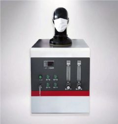
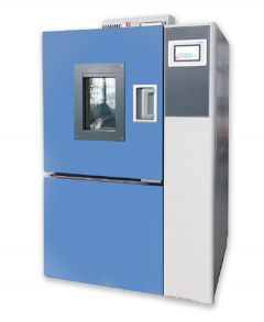 T-6549 CONSTANT TEMPERATURE AND HUMIDITY CHAMBER -FABRIC WATER VAPOR TRANSMISSION RATE
REFERENCE NUMBER: T-6549
CONSTANT TEMPERATURE AND HUMIDITY CHAMBER -FABRIC WATER VAPOR TRANSMISSION RATE
TESTING METER (WITH MOISTURE PERMEABLE CUP)
TECHNICAL DESCRIPTION OF THE INSTRUMENT:
IT IS MAINLY USED TO MEASURE THE MOISTURE PERMEABILITY OF ALL KINDS OF FABRICS, INCLUDING PERMEABLE COATED FABRICS. STRUCTURE PRINCIPLE: ADOPT COMPUTER CONTROL, CREATING A CONSTANT TEMPERATURE, AND HUMIDITY TEST ENVIRONMENT, TEST ENVIRONMENT IN THE CONSTANT TEMPERATURE, AND HUMIDITY, MOISTURE VAPOR TRANSMISSION CUP, PLACED 6 SAMPLE INTO THE GLASS AND THE RUBBER GASKET SEAL, THE CONTAINING HYGROSCOPIC AGENT OR WATER SEAL IS SPECIFIED BY THE WET CUP PLACED IN THE FABRIC SAMPLE TEMPERATURE AND HUMIDITY OF THE ENVIRONMENT, THE SEAL MOISTURE VAPOR TRANSMISSION CUP ACCORDING TO A CERTAIN TIME (INCLUDING SAMPLE AND HYGROSCOPIC AGENT OR WATER) TO CALCULATE THE MOISTURE TRANSMISSION QUALITY CHANGE.
TESTING STANDARD:
GB19082-2009 MEDICAL PRIMARY PROTECTIVE CLOTHING
TECHNICAL REQUIREMENTS GUIDELINES FOR THE SELECTION OF YY-T1498-2016 MEDICAL PROTECTIVE CLOTHING
GB/T12704.1 DETERMINATION OF MOISTURE PERMEABILITY OF FABRICS --HYGROSCOPIC METHOD
DETAILED TECHNICAL SPECIFICATIONS AND CONFIGURATION:
TECHNICAL INDICATORS:
1. TEMPERATURE CONTROL RANGE: -40°C ~ 150°C;RESOLUTION; 0.1 °C
2. HUMIDITY CONTROL RANGE: 50%RH ~ 95% RH±5%
3. SPEED RANGE: 2mm ~ 60mm/MIN
4. CONTROL PRECISION: TEMPERATURE <0.1°C; HUMIDITY + / -1% RH OR LESS
5. CYCLIC WIND SPEED: 0.02 ~ 0.5M/S, 0.3 ~ 0.5M/S
6. TIME CONTROL: 1 ~ 9999H
7. MOISTURE PERMEABLE AREA: 2827 mm 2 (DIAMETER IS 60 mm --NATIONAL STANDARD)
8. QUANTITY OF PERMEABLE CUPS: 6 GB;
9. DRYING BOX CONTROL TEMPERATURE: ROOM TEMPERATURE ~ 199 °C
10. TEST TIME: 1 ~ 999H
11. DRYING BOX STUDIO SIZE: 490 X 400 X 215mm
INSTRUMENT CONFIGURATION:
1. ONE MAIN MACHINE
QUANTITY: 1
Learn More -
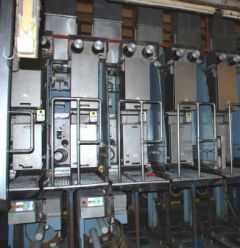 G-0784 RIETER FDY EXTRUSION EQUIPMENT FOR POLYPROPYLENE YEAR 1996/98
REFERENCE NUMBER: G-0784
RIETER FDY EXTRUSION EQUIPMENT FOR POLYPROPYLENE YEAR 1996/98
1. Machine m26/39:
Year 1996
For 1 fdy spinning line with 2+4 positions, each position with 4 ends
Product: fdy-yarn on bobbins
Raw material: pp, dried filament grade chips
Yarn count range: 150 – 400 dtex
Winder speed for target: 4000 m/min
Machine technical data:
Position gauge: 800 mm
Spinning pump capacity: 4x10 ccm/rev
Spinneret size diameter: 95 mm
Quench width: 670 mm
Quench length: 1700 mm
Number of spin-finish pumps per position: 1
Capacity of spin-finish pump: 4x0.05 ccm/rev
Number of winders/position: 1
Type of winder: riemat a6-094
Number of packages/winder: 4
Maximum package diameter: 420 mm
Package stroke: 190 mm
Package weight at 280 mm package diameter: approx. 6.2 kg
Detailed technical specifications:
Extruder for 4 positions Year 1998:
1 extruder type e1. 105-30m:
-nominal extruder capacity: max 275 kg/h for pp
-operational extruder capacity: max 248 kg/h for pp
-screw diameter: 105 mm
-l/d ratio: 30
-barrel with:
electrical ceramic heaters
7 heating zones, each zone equipped with one 2xpt100
heating zone capacity approx. 58 kw
inlet zone, water cooled
nozzle for nitrogen purge
insulation
-screw with torpedo mixing head
-reduction gear, including belt transmission to motor
-dc motor, rated power approx. 95kw
-extruder frame
1 extruder measuring head, dowtherm vapour heated
-measuring head comprising:
coarse filter
insulation
-double pt100, one each for melt and dowtherm vapour temperature
-pressure sensors for melt pressure, one in front and one behind the coarse filter
1 melt distribution system, dowtherm vapour heated
-melt distribution system comprising
main product pipe between extruder, measuring head and melt distributor.
Extruder for 2 positions Year 1998:
1 extruder type e1. 60-30
-nominal extruder capacity: max 275 kg/h for pp
-operational extruder capacity: max 248 kg/h for pp
-screw diameter: 60 mm
-l/d ratio: 30
-barrel with
electrical ceramic heaters
6 heating zones, each zone equipped with one 2xpt100
heating zone capacity approx. 17 kw
inlet zone, water cooled
insulation
-screw nitrited with maddock mixing head
-reduction gear, including belt transmission to motor
-dc motor, rated power approx. 22kw
-extruder frame
1 extruder measuring head, electrically heated year 1998
-measuring head comprising:
insulation
Double pt100, one each for melt and dowtherm vapour temperature
pressure sensors for melt pressure
burst disc for power switch-off at overpressure.
1 melt distribution system, dowtherm vapour heated
-melt distribution system comprising
main product pipe between extruder, measuring head and melt distributor.
1 riebeam bottom loading spinning beam year 1998
-beam comprising:
welded-in pump blocks with bolted pump adapter plate
silumin insulation blocks
melt distribution pipes with polished inner surfaces
efficient vapour heating on all sides of spin pumps
optimized heat condustion to the spinnerets
1 freezing valve upstream of each spinpump
2 pressure sensors for measuring the melt pressure in front and behind the spinpump
(2 per line)
heating box, completely insulated
heating by dowtherm vapour
1 double pt100 for measuring and controlling the heating box temperature
Designed as follows:
-bottom loading of rieter quickfit spinpacks
-design temperature 320°c
-maximum allowable working pressure: 300 bar for melt pipe and 2.57 bar for jacket
Dowtherm evaporator and components for heating system:
-electrically heated, total capacity approx 25 kw
-shut-off valves
-drainage valves
-dry protection sensor
-magnetic controlled level gauge
- vent system on top of measuring head.
Poy spin packs, type rieter quickfit:
-max pressure in the spinpack: 350 bar
-design temperature: 320 °c
-spinneret outside dimensions: 95 mm
-bottom loading design
-bayonet locking, insert and tighten by turning 90°
-self sealing system
-sand or metal powder filtration, 3 cm filling depth
-wire mesh filters
Spin pumps with motors and gears:
Gear pumps, 4-fold
Capacity 4 x 6 ccm/rev
Each spin pump system comprising
Individual drive motor with flange connection to the reduction gear
Hollow gear shaft for installation of spin pump shaft
Shaft with shear pin protection
Reduction ratio 1:80
Pump speed: 8-30 rev/min
Motor type: synchronous ac-motor
Rated power: 500w at 50 cps
Quench air cabinets bsk 670/1700:
Each cabinet comprising:
-rigid cabinet made from welded sheet metal, painted, side walls made from alu sheet metal
-air rectifier consisting of different layers of perforated metal sheets, rectifiers removable to the front for cleaning.
-1 perforated hinged door
-air inlet duct flanged with counter flange, comprising air flow regulating flaps
-interfloor filament duct, length 2000 mm
-alu chutes for start-up
-nozzles for connection of differential pressure gauge.
Spinning vapour exhausts:
-exhaust hood per spinning position for removal of spinning vapour
-hood designed as follows:
made from stainless steel
air flow regulation flap
hood removable for cleaning
Take-up frames, type riedraw 1:
Welded steel frame, housing all drawrolls, compressed air supply pipes for the aspirator units and the yarn waste pipes within the fdy take-up unit.
Per position:
4 inlet yarn guides
4 spin finish application nozzles
1 yarn cutter / aspirator unit
1 spin finish pump
4 centring yarn guides
4 intermingling units
rolls as described further
1 automatic winder riemat a6-094
Drawrolls year 1998:
Mono 1 with 1 rievap 32 dual shell drawroll, type j7/32-40, ot40
Speed range: 750 to 4000 mpm
Roll diameter: 190 mm
Working width: 250 mm
Temperature range: 45-250°c
And 1 bearing separator roll, type srd60 hard chromium plated
Duo 1 with 2 rievap 32 dual shell drawroll, type j7/32-60, ot40
Speedrange: 1000 to 6000 mpm
Roll diameter: 190 mm
Working width: 250 mm
Temperature range: 45-250°c
Duo 2 with 2 rievap 32 dual shell drawroll, type j7/32-60, ot40
Speedrange: 1000 to 6000 mpm
Roll diameter: 190 mm
Working width: 250 mm
Temperature range: 45-250°c
Duo 3 with 2 cold draw roll units each type j7/45-55
Speedrange: 1800 to 5500 mpm
Roll diameter: 150 mm
Working width: 180 mm
Automatic and wasteless winder riemat a6-094
Spindle driven
Number of ends per winder: 4 ends
Yarn count range: 15 to 1000 dtex
Take up speed: 2500 to 5500 m/min
Chuck length: 900 mm
190 mm stroke, 420 mm outside package diameter
Package volume: 24.7 dm³
Tube bore: 94 ±0.2 mm
Tube outside diameter: 106 ±0.4 mm
Tube length: 225 ±0.5 mm
Oil-mist lubrication unit:
Compressed air distribution station
Mobile aspirator guns with hoses
Electrical control equipment
-for electrical power
general: 3 x 380v/50hz plus ground wire
euro-standard: 3x400v 50 or 60hz plus ground wire
maximum voltage variation ±10% measured at terminals of cabinets
maximum frequency variation: ±2%
Process control system (cif):
fully integrated control system to control and monitor the entire spinning line.
the central monitoring unit si linked to the plc of the spinning section and the plcs of each spinning position.
Drive and heater control year 1998:
Spinning section:
Speed adjustment for the extruder motor is done via a dc-convertor
To achieve a constant pressure at the extruder outlet, the output of the pressure controller is transmitted to the dc-converter to adjust the extruder speed.
The feedback of the actual extruder speed is done by a tacho generator mounted on the extruder motor.
One common frequency inverter supplies the synchronous ac motors for the spin pumps.
According to process conditions, the plc transmits the setpoint to the inverter.
All motors are equipped with an overload protection.
Solid state relays heat each extruder zone and spinning beam.
Each extruder zone and the spinning beam represent an independent control loop.
Take-up section:
The inverter unit is a processor-controlled static frequency inverter for powering the 3-phase motors.
All inverter units in a position cabinet are supplied with approx 570v dc from a common rectifier.
Heating system:
The heating unit rhu is processor-controlled.
The power supply is taken straight from 3-phase 380/400v which powers the cabinet.
The inductor is fitted inside the draw roll.
The rhu switches the current on and off in this inductor. While current flows, a voltage is inducted into the
Rotating draw roll.
This sets up a short-circuit current in the draw roll, thereby heating the roll unit.
2. Machines m27/ 28 / 30 year 1998:
For 3 fdy spinning lines each with 2 positions, and each position with 4 ends
Product: fdy-yarn on bobbins
Raw material: pp, dried filament grade chips
Yarn count range: 150 – 400 dtex
Winder speed for target: 4000 m/min
Machine technical data:
Position gauge: 1000 mm
Spinning pump capacity: 4x7.5 ccm/rev
Spinneret size diameter: 95 mm
Quench width: 470 mm
Quench length: 1200 mm
Number of spin-finish pumps per position: 2
Capacity of spin-finish pump: 4x0.16 ccm/rev + 4x0,05 ccm/rev
Number of winders/position: 1
Type of winder: riemat a6-094
Number of packages/winder: 4
Maximum package diameter: 420 mm
Package stroke: 190 mm
Package weight at 280 mm package diameter: approx. 6.2 kg
Detailed technical specifications:
1 extruder type e1. 60-30m
-nominal extruder capacity: max 80 kg/h for pp
-screw diameter: 65 mm
-l/d ratio: 30
-barrel with:
electrical ceramic heaters
7 heating zones, each zone equipped with one 2xpt100
heating zone capacity approx. 22 kw
inlet zone, water cooled
nozzle for nitrogen purge
insulation
-screw with torpedo mixing head
-reduction gear, including belt transmission to motor
-dc motor, rated power approx. 22kw
-extruder frame
1 extruder measuring head, electrically heated:
-measuring head comprising:
coarse filter
insulation
-double pt100, one each for melt and dowtherm vapour temperature
-pressure sensors for melt pressure, one in front and one behind the coarse filter
1 melt distribution system, dowtherm vapour heated:
Melt distribution system comprising:
main product pipe between extruder, measuring head and melt distributor.
1 riebeam bottom loading spinning beam:
-beam comprising:
welded-in pump blocks with bolted pump adapter plate
silumin insulation blocks
melt distribution pipes with polished inner surfaces
efficient vapour heating on all sides of spin pumps
optimized heat condustion to the spinnerets
1 freezing valve upstream of each spinpump
2 pressure sensors for measuring the melt pressure in front and behind the spinpump
(2 per line)
heating box, completely insulated
heating by dowtherm vapour
1 double pt100 for measuring and controlling the heating box temperature
Designed as follows:
-bottom loading of rieter quickfit spinpacks
-design temperature 320°c
-maximum allowable working pressure: 300 bar for melt pipe and 2.57 bar for jacket
Dowtherm evaporator and components for heating system:
-electrically heated, total capacity approx 18 kw
-shut-off valves
-drainage valves
-dry protection sensor
-magnetic controlled
-level gauge
-vent system on top of measuring head.
Poy spin packs, type rieter quickfit:
Max pressure in the spinpack: 350 bar
Design temperature: 320 °c
Spinneret outside dimensions: 95 mm
Bottom loading design
Bayonet locking, insert and tighten by turning 90°
Self sealing system
Sand or metal powder filtration, 3 cm filling depth
Wire mesh filters
Spin pumps with motors and gears:
Gear pumps, 4-fold
Capacity 4 x 7.5 ccm/rev
Each spin pump system comprising
individual drive motor with flange connection to the reduction gear
hollow gear shaft for installation of spin pump shaft
shaft with shear pin protection
reduction ratio: 1:80
pump speed: 8-30 rev/min
motor type: synchronous ac-motor
rated power: 500w at 50 cps
Quench air cabinets bsk 470/1200
Each cabinet comprising:
-rigid cabinet made from welded sheet metal, painted, side walls made from alu sheet metal
-air rectifier consisting of different layers of perforated metal sheets, rectifiers removable to the front for cleaning.
-1 perforated hinged door
-air inlet duct flanged with counter flange, comprising air flow regulating flaps
-interfloor filament duct, length 2000 mm
-alu chutes for start-up
-nozzles for connection of differential pressure gauge.
Spinning vapour exhausts:
-exhaust hood per spinning position for removal of spinning vapour
-hood designed as follows:
made from stainless steel
air flow regulation flap
hood removable for cleaning
Take-up frames, type riedraw 1:
Welded steel frame, housing all drawrolls, compressed air supply pipes for the aspirator units and the yarn waste pipes within the fdy take-up unit.
Per position:
4 inlet yarn guides
2 spin finish application nozzles per end
1 yarn cutter / aspirator unit
2 spin finish pump
4 centring yarn guides
4 pre-intermingling jets
4 intermingling units
1 additional operator panel between duo1 and duo 2.
rolls as described further
1 automatic winder riemat a6-094
Drawrolls:
Mono 1 with 1 rievap 32 dual shell drawroll, type j7/32-40, ot40
Speedrange: 750 to 4000 mpm
Roll diameter: 190 mm
Working width: 250 mm
Temperature range: 45-250°c
And 1 bearing separator roll, type srd60
Hard chromium plated
Duo 1 with 2 rievap 32 dual shell drawroll, type j7/32-60, ot40
Speedrange: 1000 to 6000 mpm
Roll diameter: 190 mm
Working width: 250 mm
Temperature range: 45-250°c
Duo 2 with 2 rievap 32 dual shell drawroll, type j7/32-60, ot40
Speedrange: 1000 to 6000 mpm
Roll diameter: 190 mm
Working width: 250 mm
Temperature range: 45-250°c
Duo 3 with 2 cold draw roll units each type j7/45-55
Speedrange: 1800 to 5500 mpm
Roll diameter: 150 mm
Working width: 180 mm
Automatic and wasteless winder riemat a6-094:
Spindle driven
Number of ends per winder: 4 ends
Yarn count range: 15 to 1000 dtex
Take up speed: 2500 to 5500 m/min
Chuck length: 900 mm
190 mm stroke, 420 mm outside package diameter
Package volume: 24.7 dm³
Tube bore: 94 ± 0.2 mm
Tube outside diameter: 106 ± 0.4 mm
Tube length: 225 ± 0.5 mm
Compressed air distribution station:
Mobile aspirator guns with hoses
Electrical control equipment
For electrical power
general : 3 x 380v/50hz plus ground wire
Euro-standard: 3x400v 50 or 60hz plus ground wire
Maximum voltage variation ±10% measured at terminals of cabinets
maximum frequency variation: ±2%
Process control system (cif):
Fully integrated control system to control and monitor the entire spinning line.
The central monitoring unit si linked to the plc of the spinning section and the plcs of each spinning position.
Drive and heater control:
Spinning section.
Speed adjustment for the extruder motor is done via a dc-convertor.
To achieve a constant pressure at the extruder outlet, the output of the pressure controller is transmitted to the dc-converter to adjust the extruder speed.
The feedback of the actual extruder speed is done by a tacho generator mounted on the extruder motor.
One common frequency inverter supplies the synchronous ac motors for the spin pumps.
According to process conditions, the plc transmits the setpoint to the inverter.
All motors are equipped with an overload protection.
Solid state relays heat each extruder zone and spinning beam.
Each extruder zone and the spinning beam represent an independent control loop.
Take-up section:
The inverter unit is a processor-controlled static frequency inverter for powering the 3-phase motors.
All inverter units in a position cabinet are supplied with approx 570v dc from a common rectifier.
Heating system:
The heating unit rhu is processor-controlled.
The power supply is taken straight from 3-phase 380/400v which powers the cabinet.
The inductor is fitted inside the draw roll.
The rhu switches the current on and off in this inductor.
While current flows, a voltage is inducted into the rotating draw roll.
This sets up a short-circuit current in the draw roll, thereby heating the roll unit.
HOURLY PRODUCTION:
FOR 150 DENIER @ 3500 MPM WINDER SPEED, THE HOURLY PRODUCTION IS 3.5 KG/BOBBIN.
AS THERE IS 4 ENDS PER POSITION, THIS MEANS 14 KG/HOUR/POSITION
M26/39 ARE OF 2 + 4 POSITIONS; HENCE M26 = 28 KG/HOUR AND M39 = 56 KG/HOUR
M27/28/30 ARE OF 2 POSITIONS EACH, HENCE 28 KG/HOUR EACH.
(AS PER OUR PEOPLE AT THE EXTRUSION PLANT, THEY WERE RUNNING TRIALS TO PRODUCE THE 150 DENIER @ 4000 MPM WINDER SPEED)
FOR 300 DENIER @ 3600 MPM WINDER SPEED, THE HOURLY PRODUCTION IS 7.2 KG/BOBBIN.
AS THERE IS 4 ENDS PER POSITION, THIS MEANS 28.8 KG/HOUR/POSITION
M26/39 ARE OF 2 + 4 POSITIONS; HENCE M26 = 57.6 KG/HOUR AND M39 = 115.2 KG/HOUR
M27/28/30 ARE OF 2 POSITIONS EACH, HENCE 57.6 KG/HOUR EACH.
FOR 600 DENIER @ 2200 MPM WINDER SPEED, (SPEED LIMITATION DUE TO EXTRUDER CAPACITY) THE HOURLY PRODUCTION IS 8.8 KG/BOBBIN.
AS THERE IS 4 ENDS PER POSITION, THIS MEANS 35.2 KG/HOUR/POSITION
M26/39 ARE OF 2 + 4 POSITIONS; HENCE M26 = 70.4 KG/HOUR AND M39 = 140.8 KG/HOUR
M27/28/30 ARE OF 2 POSITIONS EACH, HENCE 70.4 KG/HOUR EACH.
MACHINE HAS BEEN PARTIALLY DISASSEMBLED (EXTRUDERS AND SPINBEAMS HAVE BEEN TAKEN DOWN TO GROUNDFLOOR) REST OF THE EQUIPMENT STILL TO BE DISASSEMBLED
Learn More -
 T-6543 MEDICAL UNIVERSAL TENSILE TESTING EQUIPMENT
REFERENCE NUMBER: T-6543
MEDICAL UNIVERSAL TENSILE TESTING EQUIPMENT
SHANDONG INDEPENDENTLY RESEARCH AND DEVELOPMENT THIS COMPREHENSIVE TESTING MACHINE FOR SURGICAL MASK & PROTECTIVE CLOTHING, IT IS WIDELY USED IN A VARIETY OF MASK STRENGTH DETECTION PROJECTS.FEATURES:COMPLY WITH NATIONAL STANDARDS, MEDICAL STANDARDS TESTING REQUIREMENTS, AUTOMATIC SOFTWARE CONTROL SYSTEM, MEET THE REQUIREMENTS OF DATA STORAGE, PRINTING, COMPARISON. THE IMPORTED SERVO MOTOR IS EQUIPPED WITH PRECISION SCREW DRIVE SYSTEM TO ENSURE THE STABILITY OF TEST DATA.
TEST STANDARDS:
GB 19082-2009 TECHNICAL REQUIREMENTS FOR DISPOSABLE PROTECTIVE CLOTHING FOR MEDICAL USE (4.5 BREAKING STRENGTH -THE BREAKING STRENGTH OF MATERIALS IN KEY PARTS OF PROTECTIVE CLOTHING SHOULD NOT BE LESS THAN 45N)
(4.6 ELONGATION AT BREAK -THE ELONGATION AT BREAK OF KEY PARTS OF PROTECTIVE CLOTHING SHOULD NOT BE LESS THAN 15%)
SELF-PRIMING FILTER RESPIRATOR FOR RESPIRATORY PROTECTION ARTICLES5.6.2 BREATHING BONNET -BREATHING BONNET SHALL BE SUBJECT TO AXIAL TENSION"DISPOSABLE MASK: 10N FOR 10S" "REPLACEABLE MASK: 50N FOR 10S"
(5.9 HEADBAND -HEADBAND SHOULD BEAR THE TENSION "DISPOSABLE MASK: 10N, 10S" "REPLACEABLE HALF MASK: 50N FOR 10S" "FULL MASK: 150N FOR 10S")
5.10 JOINTS AND CONNECTING PARTS -JOINTS AND CONNECTING PARTS SHALL BE SUBJECT TO AXIAL TENSION
"REPLACEABLE HALF MASK: 50N FOR 10S" "FULL COVER 250N FOR 10S"
GB/T 32610-2016 TECHNICAL SPECIFICATION FOR DAILY PROTECTIVE MASKS
(6.9 BREAKING STRENGTH OF THE MASK BELT AND THE CONNECTION BETWEEN THE MASK BELT ANDTHE MASK BODY ≥ 20N)
(6.10 FASTNESS TO BREATHING BONNET: NO SLIPPAGE, BREAKAGE OR DEFORMATION SHALL OCCUR)
YY/T 0699-2013 DISPOSABLE SURGICAL MASK
(4.4 MASK BELT -THE BREAKING FORCE AT THE CONNECTION POINT BETWEEN EACH MASK BELT AND THE MASK BODY IS NOT LESS THAN 10N)
YY 0469-2011 SURGICAL MASK FOR MEDICAL USE (5.4.2 MASK BELT)
GB/T 3923.1-1997 DETERMINATION OF BREAKING STRENGTH AND ELONGATION AT BREAK OF FABRICS (STRIP METHOD)
DISPOSABLE RUBBER INSPECTION GLOVES (6.3 TENSILE PROPERTIES)
INSTRUMENT TECHNICAL PARAMETERS:
SPECIFICATION: 200N (STANDARD) 50N, 100N, 500N, 1000N (OPTIONAL)
ACCURACY: BETTER THAN 0.5RESOLUTION OF FORCE VALUE: 0.1N
DEFORMATION RESOLUTION: 0.001mm
TEST SPEED: 0.01mm/MIN ~ 2000mm/MIN (STEPLESS SPEED REGULATION)
WIDTH OF SAMPLE: 30mm (STANDARD FIXTURE) 50mm (OPTIONAL FIXTURE)
CLAMPING OF SAMPLES: MANUAL (PNEUMATIC CLAMPING CAN BE CHANGED)
STROKE: 700mm (STANDARD) 400mm, 1000mm (OPTIONAL)
QUANTITY: 1
Learn More -
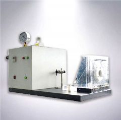 T-6544 SYNTHETIC BLOOD PENETRATION TESTER FOR SURGICAL MASK
REFERENCE NUMBER: T-6544
SYNTHETIC BLOOD PENETRATION TESTER FOR SURGICAL MASK
TECHNICAL INDICATORS:
1. THE PROTRUDING SAMPLE FIXING DEVICE CAN SIMULATE THE ACTUAL USE STATE OF THE MASK, SET ASIDE THE TEST TARGET AREA WITHOUT DESTROYING THE SAMPLE, AND DISTRIBUTE THE SYNTHETIC BLOOD IN THE TARGET AREA OF THE SAMPLE.
2. THE SPECIAL FIXED-PRESSURE INJECTION DEVICE CAN EJECT A CERTAIN VOLUME OF SYNTHETIC BLOOD IN A CONTROLLED TIME.
3. IT CAN FULLY SIMULATE THE INJECTION SPEED CORRESPONDING TO THE AVERAGE BLOOD PRESSURE OF HUMAN BODY OF 10.6KPA, 16KPA AND 21.3KPA.
4. A FIXED TARGET PLATE IS SET TO BLOCK THE HIGH-PRESSURE EDGE PART OF THE INJECTED LIQUID FLOW AND ONLY ALLOW THE STEADY FLOW PART TO BE SPRAYED ON THE SAMPLE, WHICH INCREASES THE ACCURACY AND REPEATABILITY OF THE LIQUID VELOCITY SPRAYED ON THE SAMPLE.
STANDARDS:
MEDICAL RESPIRATOR TECHNICAL REQUIREMENTS, 5.5 SYNTHETIC BLOOD PENETRATION BARRIER PERFORMANCE
YY/T 0691-2008 INFECTIOUS PATHOGEN PROTECTION EQUIPMENT MEDICAL MASK RESISTANCE TO SYNTHETIC BLOOD PENETRABILITY TEST METHOD (FIXED VOLUME, HORIZONTAL INJECTION)
YY 0469-2011 MEDICAL SURGICAL MASK TECHNOLOGY REQUIRES A BLOOD PENETRATION TEST DEVICE
ISO 22609:2004 INFECTIOUS PATHOGEN PROTECTION EQUIPMENT MEDICAL MASK TEST METHOD FOR RESISTANCE TO SYNTHETIC BLOOD PENETRATION (FIXED VOLUME, HORIZONTAL INJECTION)
ASTM F1862-07 STANDARD TEST METHOD FOR RESISTANCE OF MEDICAL FACE MASKS TO BLOT BY SYNTHETIC BLOOD (HORIZONTAL PROJECTION OF FIXED VOLUME AT A KNOW VELOCITY)
TECHNICAL PARAMETERS:
1. INJECTION DISTANCE: 300mm ~ 305mm ADJUSTABLE
2. NOZZLE DIAMETER: 0.84mm
3. INJECTION SPEED: 450CM/S, 550CM/S, 635CM/S
4. WEIGHT: 35KG
5. POWER SOURCE: AC220V 50HZ
QUANTITY: 1
Learn More -
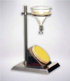 T-6548 FABRIC SURFACE WETTING TESTER
REFERENCE NUMBER: T-6548
FABRIC SURFACE WETTING TESTER
INSTRUMENT TECHNICAL DESCRIPTION:
WATER TESTER IS TO INSTALL THE SAMPLE ON THE SAMPLE HOLDER AND MAKE AN ANGLE OF 45 ° WITH THE LEVEL. THE CENTER OF THE SAMPLE IS LOCATED AT A SPECIFIED DISTANCE BELOW THE NOZZLE. THE SAMPLE IS SPRAYED WITH A SPECIFIED VOLUME OF DISTILLED OR DEIONIZED WATER. BY COMPARING THE APPEARANCE OF THE SAMPLE WITH THE EVALUATION STANDARDS AND PICTURES TO DETERMINE ITS WATER-SOAKING GRADE, IT IS SUITABLE FOR MEASURING VARIOUS WATER-SOAKING TESTS ON THE SURFACE OF FABRICS WITH OR WITHOUT WATER RESISTANCE AND WATER REPELLENT FINISHING. THIS INSTRUMENT IS NOT SUITABLE FOR MEASURING THE WATER PERMEABILITY OF FABRICS, SO IT CANNOT BE USED TO PREDICT THE RAINPROOF PERMEABILITY OF FABRICS.
STANDARD:
GB19082-2009 TECHNICAL REQUIREMENTS FOR MEDICAL PRIMARY PROTECTIVE CLOTHINGGB / T4745 SURFACE MOISTURE RESISTANCE TEST
THE MAIN TECHNICAL INDICATORS OF THE INSTRUMENT:
GLASS FUNNEL: φ150mm
MEASURING CUP: 500ML
SAMPLE SUPPORT ANGLE: 45 °
INSTRUMENT CONFIGURATION:
1. ONE HOST
2. A GLASS FUNNEL
3. 500ML MEASURING CUP
QUANTITY: 1
Learn More -
 T-6547 RESPIRATOR RESISTANCE TESTER FOR FACE MASKS
REFERENCE NUMBER: T-6547
RESPIRATOR RESISTANCE TESTER FOR FACE MASKS
INTRODUCTION
THE RESPIRATOR RESISTANCE TESTER IS USED TO MEASURE THE INSPIRATORY RESISTANCE AND EXPIRATORY RESISTANCE OF RESPIRATORS AND RESPIRATOR PROTECTORS UNDER SPECIFIED CONDITIONS. IT IS APPLICABLE TO THE NATIONAL LABOR PROTECTION EQUIPMENT INSPECTION INSTITUTIONS, MASK MANUFACTURERS FOR THE GENERAL MASKS, DUST MASKS, MEDICAL MASKS, ANTI-SMOG MASKS PRODUCTS OF THE RELEVANT TESTING AND INSPECTION.
STANDARD
GB 19083-2010 TECHNICAL REQUIREMENTS FOR MEDICAL PROTECTIVE MASKS
GB 2626-2006 RESPIRATOR SELF-SUCTION FILTER RESPIRATOR AGAINST PARTICULATE MATTER
GB/T 32610-2016 TECHNICAL SPECIFICATIONS FOR DAILY PROTECTIVE MASKS
FEATURES:
1. HIGH-DEFINITION LCD DISPLAY.
2. DIGITAL DIFFERENTIAL PRESSURE METER WITH HIGH PRECISION IMPORTED BRAND.
3. HIGH PRECISION IMPORTED BRAND OF DIGITAL FLOWMETER, WITH HIGH FLOW CONTROL ACCURACY FEATURES.
4. THE RESPIRATOR RESISTANCE TESTER CAN SET UP TWO MODES: EXHALATION DETECTION AND INHALATION DETECTION.
5. AUTOMATIC PIPELINE SWITCHING DEVICE OF RESPIRATOR SOLVES THE PROBLEM OF PIPE EXTUBATION AND WRONG CONNECTION WHEN TESTING.
PARAMETER:
1. FLOWMETER RANGE: 0 ~ 100L/MIN, ACCURACY IS 3%
2. DIGITAL PRESSURE DIFFERENCE METER RANGE: 0 ~ 2000PA, ACCURACY: 1PA
3. PUMPING CAPACITY OF AIR PUMP: >100L/MIN
4. OVERALL SIZE: 460 X 1080 X 670mm
5. POWER SOURCE: AC220V 50HZ 650W
6. WEIGHT: 55KG
QUANTITY: 1
Learn More -
 T-6550 MEDICAL PROTECTIVE CLOTHING BLOOD SYNTHETIC PENETRABILITY TESTER
REFERENCE NUMBER: T-6550
MEDICAL PROTECTIVE CLOTHING BLOOD SYNTHETIC PENETRABILITY TESTER
TECHNICAL SPECIFICATIONS AND CONFIGURATION:
1. THE INSTRUMENT ADOPTS AN AIR SOURCE THAT CAN PROVIDE (0.5 ~ 30±0.1) KPA PRESSURE TO CONTINUOUSLY PRESSURIZED THE SAMPLE, WHICH IS NOT RESTRICTED BY THE SPACE OF THE TEST SITE;
2. THE AIR PRESSURE RANGE CAN BE ADJUSTED FREELY, AND THE ADJUSTMENT RANGE (0.5 ~ 30) KPA;
3. COLOR TOUCH SCREEN DISPLAY AND OPERATION;
4. THE SAMPLE CLAMPING PAD IS PROCESSED WITH IMPORTED SPECIAL ALUMINUM PROFILES, WHICH IS LIGHT IN MATERIAL, CLEAN IN SURFACE AND NEVER RUSTS.
5. THE INSTRUMENT ADOPTS IMPORTED SPECIAL ALUMINUM WIRE DRAWING PANEL, EQUIPPED WITH METAL KEYS, SENSITIVE OPERATION, NOT EASY TO DAMAGE;
6. CLAMPING DEVICE FOR INSTRUMENT SAMPLES, EQUIPPED WITH LOCKING PROTECTION, TO PREVENT THE SYNTHETIC BLOOD FROM SPLASHING AROUND;
7. CLAMPING FORCE IS ACCURATE AND RELIABLE;
8. THE TEST TANK IS EQUIPPED WITH A SPECIAL PLACEMENT DEVICE, WHICH IS CONVENIENT FOR CUSTOMERS TO OPERATE;
9. THE TEST TANK IS PROCESSED WITH SPECIAL 316 STAINLESS STEEL, AND THE TOP IS EQUIPPED WITH A SPECIAL COVER FOR HIGH TRANSPARENT PROTECTION;
10. THE WASHER BELOW THE SAMPLE IS MADE OF HIGH-QUALITY PTFE MATERIAL AFTER SPECIAL PROCESSING;
11. SQUARE METAL BLOCK NET: OPEN SPACE ≥50°%; BENDING ≤5mm AT 30KPA;
12. INSTRUMENT TIME CONTROL ACCURACY ≤01 SECONDS;
13. THE SHELL OF THE INSTRUMENT IS MADE OF HIGH-QUALITY METAL BAKING PAINT, WHICH IS BEAUTIFUL AND GENEROUS.
14. EQUIPPED WITH PRINTER INTERFACE, CONNECTED TO THE PRINTER CAN DIRECTLY PRINT DATA REPORTS.
TECHNICAL PARAMETERS:
1. SAMPLE SIZE: 75mm X 75mm
2. TEST AREA: 28.26 SQUARE CENTIMETERS
3. AIR PRESSURE ADJUSTMENT RANGE (0.5 ~ 30) KPA
4. EXTERNAL SIZE: 500mm X 500mm X 500mm (L X W X H)
5. WEIGHT OF THE INSTRUMENT: 40 KG
6. POWER SUPPLY: AC220V, 50HZ,SCOPE OF SUPPLY: 1. ONE MAIN MACHINE; 2. TWO PTFE GASKETS; 3. TWO ORDINARY WASHERS; 4. ONE METAL BLOCKING NET; 5. A SET OF SPECIAL LOCKING TOOLS; 6. ONE HIGH-QUALITY SILENT AIR PUMP, [NOTE: SAFETY PRODUCTION LICENSE IS NOT INCLUDED]. 7. EQUIPPED WITH PRINTER INTERFACE; 8. ONE SAMPLE TEMPLATE; 9. ONE PRODUCT CERTIFICATE; 10. ONE COPY OF PRODUCT OPERATION MANUAL.
OPERATION INSTRUCTION:
INSERT THE AIR PUMP OUTPUT PIPE INTO THE OIL AND WATER SEPARATOR OF THE INSTRUMENT AS REQUIRED (PRESSURE 0.1-0.3MPA).
AFTER SWITCHING ON THE POWER, THE STARTUP INTERFACE (NAME OF THE DEVICE) IS DISPLAYED.
PRESS THE "ENTER" BUTTON TO ENTER THE TEST INTERFACE, AS SHOWN IN THE FOLLOWING FIGURE:
CLICK "SETTING” BUTTON, GET INTO PARAMETER SETTING SCREEN, AS BELOW THIS SCREEN CAN SET THE SYSTEM TIME, DATE AND TESTING TIME, AFTER SETTING, CLICK "SAVE” BUTTON TO KEEP THE SETTING DATA. (NOTE: IT REQUIRES 5 MINUTES IN THE STANDARD)
QUANTITY: 1
Learn More -
 T-6551 MASK FLAME RETARDANT PERFORMANCE TESTER
REFERENCE NUMBER: T-6551
MASK FLAME RETARDANT PERFORMANCE TESTER
MASK FLAME RETARDANT PERFORMANCE TESTER
TECHNICAL INDEX:
1.THE LINEAR VELOCITY OF THE NOSE TIP OF THE DIE IS (60 ± 5) MM / S
2.THE DIAMETER OF FLAME TEMPERATURE MEASURINGPROBE IS 1.5MM
3.THE FLAME TEMPERATURE IS (800 ± 50) °C
4.THE DISTANCE BETWEEN THE BURNER TOP AND THE MASK IS (20 ± 2) MM
5.METAL DIE
APPLICABLE STANDARD:
GB 19083-2010 TECHNICAL REQUIREMENTS FOR MEDICAL PROTECTIVE MASKS
YY 0469-2011 MEDICAL SURGICAL MASK
MEDICAL PROTECTIVE MASK REFERS TO A SELF-PRIMING FILTER TYPE DUST-PROOF MEDICAL PROTECTIVE MASK THAT CAN FILTER THE PARTICLES IN THE AIR AND BLOCK THE DROPLETS, BLOOD, BODY FLUIDS, SECRETIONS, ETC.
QUANTITY: 1
Learn More -
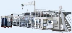 M-5300 UNDER PAD PRODUCTION LINEREFERENCE NUMBER: M-5300 (131342BVGT12UF) L UNDER PAD PRODUCTION LINE UNDER PAD PRODUCTION LINE MODEL: 100CD PRODUCTS TO BE PRODUCED: 3 SIZES OF DISPOSABLE UNDER PAD (SIZE: 600x900mm, 600x600mm, 600x400mm) MECHANICAL DRIVING SYSTEM WITH INVERTER CONTROL PRODUCT STRUCTURE: FLUFF +SAP; TOP TISSUE; BOTTOM TISSUE; TOP SHEET; BACK SHEET QUANTITY AVAILABLE: 1 Learn More
 -
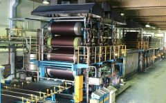 M-5281 IRA GRIFFIN INDIGO DYEING LINE FOR DENIM YEAR 2005REFERENCE NUMBER: M-5281 (1313DGFFXX12) L IRA GRIFFIN INDIGO DYEING LINE FOR DENIM YEAR 2005 INDIGO DYEING LINE FOR DENIM (1) X DIRECT WARPING MACHINE WESTPOINT USA YEAR 2005 (1) X INDIGO DENIM COLORING PLANT IRA GRIFFING USA YEAR 2005 (13) X BOX DYEING COLORING DEVICES QUANTITY AVAILABLE: 1 Learn More