Search results for: 'lock in'
- Related search terms
- lockstitch quilt
- Lock
- Lock stitch qui
- Lock s
- Lock stit
-
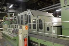
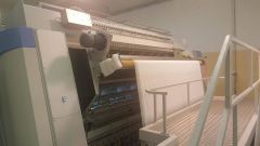
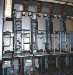 G-0784 RIETER FDY EXTRUSION EQUIPMENT FOR POLYPROPYLENE YEAR 1996/98
REFERENCE NUMBER: G-0784
RIETER FDY EXTRUSION EQUIPMENT FOR POLYPROPYLENE YEAR 1996/98
1. Machine m26/39:
Year 1996
For 1 fdy spinning line with 2+4 positions, each position with 4 ends
Product: fdy-yarn on bobbins
Raw material: pp, dried filament grade chips
Yarn count range: 150 – 400 dtex
Winder speed for target: 4000 m/min
Machine technical data:
Position gauge: 800 mm
Spinning pump capacity: 4x10 ccm/rev
Spinneret size diameter: 95 mm
Quench width: 670 mm
Quench length: 1700 mm
Number of spin-finish pumps per position: 1
Capacity of spin-finish pump: 4x0.05 ccm/rev
Number of winders/position: 1
Type of winder: riemat a6-094
Number of packages/winder: 4
Maximum package diameter: 420 mm
Package stroke: 190 mm
Package weight at 280 mm package diameter: approx. 6.2 kg
Detailed technical specifications:
Extruder for 4 positions Year 1998:
1 extruder type e1. 105-30m:
-nominal extruder capacity: max 275 kg/h for pp
-operational extruder capacity: max 248 kg/h for pp
-screw diameter: 105 mm
-l/d ratio: 30
-barrel with:
electrical ceramic heaters
7 heating zones, each zone equipped with one 2xpt100
heating zone capacity approx. 58 kw
inlet zone, water cooled
nozzle for nitrogen purge
insulation
-screw with torpedo mixing head
-reduction gear, including belt transmission to motor
-dc motor, rated power approx. 95kw
-extruder frame
1 extruder measuring head, dowtherm vapour heated
-measuring head comprising:
coarse filter
insulation
-double pt100, one each for melt and dowtherm vapour temperature
-pressure sensors for melt pressure, one in front and one behind the coarse filter
1 melt distribution system, dowtherm vapour heated
-melt distribution system comprising
main product pipe between extruder, measuring head and melt distributor.
Extruder for 2 positions Year 1998:
1 extruder type e1. 60-30
-nominal extruder capacity: max 275 kg/h for pp
-operational extruder capacity: max 248 kg/h for pp
-screw diameter: 60 mm
-l/d ratio: 30
-barrel with
electrical ceramic heaters
6 heating zones, each zone equipped with one 2xpt100
heating zone capacity approx. 17 kw
inlet zone, water cooled
insulation
-screw nitrited with maddock mixing head
-reduction gear, including belt transmission to motor
-dc motor, rated power approx. 22kw
-extruder frame
1 extruder measuring head, electrically heated year 1998
-measuring head comprising:
insulation
Double pt100, one each for melt and dowtherm vapour temperature
pressure sensors for melt pressure
burst disc for power switch-off at overpressure.
1 melt distribution system, dowtherm vapour heated
-melt distribution system comprising
main product pipe between extruder, measuring head and melt distributor.
1 riebeam bottom loading spinning beam year 1998
-beam comprising:
welded-in pump blocks with bolted pump adapter plate
silumin insulation blocks
melt distribution pipes with polished inner surfaces
efficient vapour heating on all sides of spin pumps
optimized heat condustion to the spinnerets
1 freezing valve upstream of each spinpump
2 pressure sensors for measuring the melt pressure in front and behind the spinpump
(2 per line)
heating box, completely insulated
heating by dowtherm vapour
1 double pt100 for measuring and controlling the heating box temperature
Designed as follows:
-bottom loading of rieter quickfit spinpacks
-design temperature 320°c
-maximum allowable working pressure: 300 bar for melt pipe and 2.57 bar for jacket
Dowtherm evaporator and components for heating system:
-electrically heated, total capacity approx 25 kw
-shut-off valves
-drainage valves
-dry protection sensor
-magnetic controlled level gauge
- vent system on top of measuring head.
Poy spin packs, type rieter quickfit:
-max pressure in the spinpack: 350 bar
-design temperature: 320 °c
-spinneret outside dimensions: 95 mm
-bottom loading design
-bayonet locking, insert and tighten by turning 90°
-self sealing system
-sand or metal powder filtration, 3 cm filling depth
-wire mesh filters
Spin pumps with motors and gears:
Gear pumps, 4-fold
Capacity 4 x 6 ccm/rev
Each spin pump system comprising
Individual drive motor with flange connection to the reduction gear
Hollow gear shaft for installation of spin pump shaft
Shaft with shear pin protection
Reduction ratio 1:80
Pump speed: 8-30 rev/min
Motor type: synchronous ac-motor
Rated power: 500w at 50 cps
Quench air cabinets bsk 670/1700:
Each cabinet comprising:
-rigid cabinet made from welded sheet metal, painted, side walls made from alu sheet metal
-air rectifier consisting of different layers of perforated metal sheets, rectifiers removable to the front for cleaning.
-1 perforated hinged door
-air inlet duct flanged with counter flange, comprising air flow regulating flaps
-interfloor filament duct, length 2000 mm
-alu chutes for start-up
-nozzles for connection of differential pressure gauge.
Spinning vapour exhausts:
-exhaust hood per spinning position for removal of spinning vapour
-hood designed as follows:
made from stainless steel
air flow regulation flap
hood removable for cleaning
Take-up frames, type riedraw 1:
Welded steel frame, housing all drawrolls, compressed air supply pipes for the aspirator units and the yarn waste pipes within the fdy take-up unit.
Per position:
4 inlet yarn guides
4 spin finish application nozzles
1 yarn cutter / aspirator unit
1 spin finish pump
4 centring yarn guides
4 intermingling units
rolls as described further
1 automatic winder riemat a6-094
Drawrolls year 1998:
Mono 1 with 1 rievap 32 dual shell drawroll, type j7/32-40, ot40
Speed range: 750 to 4000 mpm
Roll diameter: 190 mm
Working width: 250 mm
Temperature range: 45-250°c
And 1 bearing separator roll, type srd60 hard chromium plated
Duo 1 with 2 rievap 32 dual shell drawroll, type j7/32-60, ot40
Speedrange: 1000 to 6000 mpm
Roll diameter: 190 mm
Working width: 250 mm
Temperature range: 45-250°c
Duo 2 with 2 rievap 32 dual shell drawroll, type j7/32-60, ot40
Speedrange: 1000 to 6000 mpm
Roll diameter: 190 mm
Working width: 250 mm
Temperature range: 45-250°c
Duo 3 with 2 cold draw roll units each type j7/45-55
Speedrange: 1800 to 5500 mpm
Roll diameter: 150 mm
Working width: 180 mm
Automatic and wasteless winder riemat a6-094
Spindle driven
Number of ends per winder: 4 ends
Yarn count range: 15 to 1000 dtex
Take up speed: 2500 to 5500 m/min
Chuck length: 900 mm
190 mm stroke, 420 mm outside package diameter
Package volume: 24.7 dm³
Tube bore: 94 ±0.2 mm
Tube outside diameter: 106 ±0.4 mm
Tube length: 225 ±0.5 mm
Oil-mist lubrication unit:
Compressed air distribution station
Mobile aspirator guns with hoses
Electrical control equipment
-for electrical power
general: 3 x 380v/50hz plus ground wire
euro-standard: 3x400v 50 or 60hz plus ground wire
maximum voltage variation ±10% measured at terminals of cabinets
maximum frequency variation: ±2%
Process control system (cif):
fully integrated control system to control and monitor the entire spinning line.
the central monitoring unit si linked to the plc of the spinning section and the plcs of each spinning position.
Drive and heater control year 1998:
Spinning section:
Speed adjustment for the extruder motor is done via a dc-convertor
To achieve a constant pressure at the extruder outlet, the output of the pressure controller is transmitted to the dc-converter to adjust the extruder speed.
The feedback of the actual extruder speed is done by a tacho generator mounted on the extruder motor.
One common frequency inverter supplies the synchronous ac motors for the spin pumps.
According to process conditions, the plc transmits the setpoint to the inverter.
All motors are equipped with an overload protection.
Solid state relays heat each extruder zone and spinning beam.
Each extruder zone and the spinning beam represent an independent control loop.
Take-up section:
The inverter unit is a processor-controlled static frequency inverter for powering the 3-phase motors.
All inverter units in a position cabinet are supplied with approx 570v dc from a common rectifier.
Heating system:
The heating unit rhu is processor-controlled.
The power supply is taken straight from 3-phase 380/400v which powers the cabinet.
The inductor is fitted inside the draw roll.
The rhu switches the current on and off in this inductor. While current flows, a voltage is inducted into the
Rotating draw roll.
This sets up a short-circuit current in the draw roll, thereby heating the roll unit.
2. Machines m27/ 28 / 30 year 1998:
For 3 fdy spinning lines each with 2 positions, and each position with 4 ends
Product: fdy-yarn on bobbins
Raw material: pp, dried filament grade chips
Yarn count range: 150 – 400 dtex
Winder speed for target: 4000 m/min
Machine technical data:
Position gauge: 1000 mm
Spinning pump capacity: 4x7.5 ccm/rev
Spinneret size diameter: 95 mm
Quench width: 470 mm
Quench length: 1200 mm
Number of spin-finish pumps per position: 2
Capacity of spin-finish pump: 4x0.16 ccm/rev + 4x0,05 ccm/rev
Number of winders/position: 1
Type of winder: riemat a6-094
Number of packages/winder: 4
Maximum package diameter: 420 mm
Package stroke: 190 mm
Package weight at 280 mm package diameter: approx. 6.2 kg
Detailed technical specifications:
1 extruder type e1. 60-30m
-nominal extruder capacity: max 80 kg/h for pp
-screw diameter: 65 mm
-l/d ratio: 30
-barrel with:
electrical ceramic heaters
7 heating zones, each zone equipped with one 2xpt100
heating zone capacity approx. 22 kw
inlet zone, water cooled
nozzle for nitrogen purge
insulation
-screw with torpedo mixing head
-reduction gear, including belt transmission to motor
-dc motor, rated power approx. 22kw
-extruder frame
1 extruder measuring head, electrically heated:
-measuring head comprising:
coarse filter
insulation
-double pt100, one each for melt and dowtherm vapour temperature
-pressure sensors for melt pressure, one in front and one behind the coarse filter
1 melt distribution system, dowtherm vapour heated:
Melt distribution system comprising:
main product pipe between extruder, measuring head and melt distributor.
1 riebeam bottom loading spinning beam:
-beam comprising:
welded-in pump blocks with bolted pump adapter plate
silumin insulation blocks
melt distribution pipes with polished inner surfaces
efficient vapour heating on all sides of spin pumps
optimized heat condustion to the spinnerets
1 freezing valve upstream of each spinpump
2 pressure sensors for measuring the melt pressure in front and behind the spinpump
(2 per line)
heating box, completely insulated
heating by dowtherm vapour
1 double pt100 for measuring and controlling the heating box temperature
Designed as follows:
-bottom loading of rieter quickfit spinpacks
-design temperature 320°c
-maximum allowable working pressure: 300 bar for melt pipe and 2.57 bar for jacket
Dowtherm evaporator and components for heating system:
-electrically heated, total capacity approx 18 kw
-shut-off valves
-drainage valves
-dry protection sensor
-magnetic controlled
-level gauge
-vent system on top of measuring head.
Poy spin packs, type rieter quickfit:
Max pressure in the spinpack: 350 bar
Design temperature: 320 °c
Spinneret outside dimensions: 95 mm
Bottom loading design
Bayonet locking, insert and tighten by turning 90°
Self sealing system
Sand or metal powder filtration, 3 cm filling depth
Wire mesh filters
Spin pumps with motors and gears:
Gear pumps, 4-fold
Capacity 4 x 7.5 ccm/rev
Each spin pump system comprising
individual drive motor with flange connection to the reduction gear
hollow gear shaft for installation of spin pump shaft
shaft with shear pin protection
reduction ratio: 1:80
pump speed: 8-30 rev/min
motor type: synchronous ac-motor
rated power: 500w at 50 cps
Quench air cabinets bsk 470/1200
Each cabinet comprising:
-rigid cabinet made from welded sheet metal, painted, side walls made from alu sheet metal
-air rectifier consisting of different layers of perforated metal sheets, rectifiers removable to the front for cleaning.
-1 perforated hinged door
-air inlet duct flanged with counter flange, comprising air flow regulating flaps
-interfloor filament duct, length 2000 mm
-alu chutes for start-up
-nozzles for connection of differential pressure gauge.
Spinning vapour exhausts:
-exhaust hood per spinning position for removal of spinning vapour
-hood designed as follows:
made from stainless steel
air flow regulation flap
hood removable for cleaning
Take-up frames, type riedraw 1:
Welded steel frame, housing all drawrolls, compressed air supply pipes for the aspirator units and the yarn waste pipes within the fdy take-up unit.
Per position:
4 inlet yarn guides
2 spin finish application nozzles per end
1 yarn cutter / aspirator unit
2 spin finish pump
4 centring yarn guides
4 pre-intermingling jets
4 intermingling units
1 additional operator panel between duo1 and duo 2.
rolls as described further
1 automatic winder riemat a6-094
Drawrolls:
Mono 1 with 1 rievap 32 dual shell drawroll, type j7/32-40, ot40
Speedrange: 750 to 4000 mpm
Roll diameter: 190 mm
Working width: 250 mm
Temperature range: 45-250°c
And 1 bearing separator roll, type srd60
Hard chromium plated
Duo 1 with 2 rievap 32 dual shell drawroll, type j7/32-60, ot40
Speedrange: 1000 to 6000 mpm
Roll diameter: 190 mm
Working width: 250 mm
Temperature range: 45-250°c
Duo 2 with 2 rievap 32 dual shell drawroll, type j7/32-60, ot40
Speedrange: 1000 to 6000 mpm
Roll diameter: 190 mm
Working width: 250 mm
Temperature range: 45-250°c
Duo 3 with 2 cold draw roll units each type j7/45-55
Speedrange: 1800 to 5500 mpm
Roll diameter: 150 mm
Working width: 180 mm
Automatic and wasteless winder riemat a6-094:
Spindle driven
Number of ends per winder: 4 ends
Yarn count range: 15 to 1000 dtex
Take up speed: 2500 to 5500 m/min
Chuck length: 900 mm
190 mm stroke, 420 mm outside package diameter
Package volume: 24.7 dm³
Tube bore: 94 ± 0.2 mm
Tube outside diameter: 106 ± 0.4 mm
Tube length: 225 ± 0.5 mm
Compressed air distribution station:
Mobile aspirator guns with hoses
Electrical control equipment
For electrical power
general : 3 x 380v/50hz plus ground wire
Euro-standard: 3x400v 50 or 60hz plus ground wire
Maximum voltage variation ±10% measured at terminals of cabinets
maximum frequency variation: ±2%
Process control system (cif):
Fully integrated control system to control and monitor the entire spinning line.
The central monitoring unit si linked to the plc of the spinning section and the plcs of each spinning position.
Drive and heater control:
Spinning section.
Speed adjustment for the extruder motor is done via a dc-convertor.
To achieve a constant pressure at the extruder outlet, the output of the pressure controller is transmitted to the dc-converter to adjust the extruder speed.
The feedback of the actual extruder speed is done by a tacho generator mounted on the extruder motor.
One common frequency inverter supplies the synchronous ac motors for the spin pumps.
According to process conditions, the plc transmits the setpoint to the inverter.
All motors are equipped with an overload protection.
Solid state relays heat each extruder zone and spinning beam.
Each extruder zone and the spinning beam represent an independent control loop.
Take-up section:
The inverter unit is a processor-controlled static frequency inverter for powering the 3-phase motors.
All inverter units in a position cabinet are supplied with approx 570v dc from a common rectifier.
Heating system:
The heating unit rhu is processor-controlled.
The power supply is taken straight from 3-phase 380/400v which powers the cabinet.
The inductor is fitted inside the draw roll.
The rhu switches the current on and off in this inductor.
While current flows, a voltage is inducted into the rotating draw roll.
This sets up a short-circuit current in the draw roll, thereby heating the roll unit.
HOURLY PRODUCTION:
FOR 150 DENIER @ 3500 MPM WINDER SPEED, THE HOURLY PRODUCTION IS 3.5 KG/BOBBIN.
AS THERE IS 4 ENDS PER POSITION, THIS MEANS 14 KG/HOUR/POSITION
M26/39 ARE OF 2 + 4 POSITIONS; HENCE M26 = 28 KG/HOUR AND M39 = 56 KG/HOUR
M27/28/30 ARE OF 2 POSITIONS EACH, HENCE 28 KG/HOUR EACH.
(AS PER OUR PEOPLE AT THE EXTRUSION PLANT, THEY WERE RUNNING TRIALS TO PRODUCE THE 150 DENIER @ 4000 MPM WINDER SPEED)
FOR 300 DENIER @ 3600 MPM WINDER SPEED, THE HOURLY PRODUCTION IS 7.2 KG/BOBBIN.
AS THERE IS 4 ENDS PER POSITION, THIS MEANS 28.8 KG/HOUR/POSITION
M26/39 ARE OF 2 + 4 POSITIONS; HENCE M26 = 57.6 KG/HOUR AND M39 = 115.2 KG/HOUR
M27/28/30 ARE OF 2 POSITIONS EACH, HENCE 57.6 KG/HOUR EACH.
FOR 600 DENIER @ 2200 MPM WINDER SPEED, (SPEED LIMITATION DUE TO EXTRUDER CAPACITY) THE HOURLY PRODUCTION IS 8.8 KG/BOBBIN.
AS THERE IS 4 ENDS PER POSITION, THIS MEANS 35.2 KG/HOUR/POSITION
M26/39 ARE OF 2 + 4 POSITIONS; HENCE M26 = 70.4 KG/HOUR AND M39 = 140.8 KG/HOUR
M27/28/30 ARE OF 2 POSITIONS EACH, HENCE 70.4 KG/HOUR EACH.
MACHINE HAS BEEN PARTIALLY DISASSEMBLED (EXTRUDERS AND SPINBEAMS HAVE BEEN TAKEN DOWN TO GROUNDFLOOR) REST OF THE EQUIPMENT STILL TO BE DISASSEMBLED
Learn More -
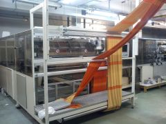
 SPINNBAU NONWOVEN LINE, YEAR 1994REFERENCE NUMBER: T-6843 SPINNBAU NONWOVEN LINE, YEAR 1994 BRAND: SPINNBAU SHORT DESCRIPTION: NONWOVEN LINE YEAR: 1994 NONWOVEN LINE CONSISTING OF 1. CARD FEEDING: CARD FEEDING R&S, NEW, IN 2500mm WORKING WIDTH, CONSISTING OF: ONE R&S MATERIAL BIN IN 2500mm WORKING WIDTH, 600mm DEPTH AND A COMPLETE HEIGHT OF 2500mm, WITH TOP AND BOTTOM WINDOW AT BOTH SIDES, FILLING LEVEL CONTROLLED BY IN HEIGHT ADJUSTABLE INFRARED DEVICES. ONE DOOR AT THE BACKSIDE FOR CLEANING, LOCKED BY SECURITY SWITCHES. THE VITIATED AIR ESCAPES THROUGH THE PERFORATED SHEETMETAL AT THE TOP. THESE AREAS ARE COMPLETELY COVERED, THE OUTGOING AIR CAN BE FILTERED BY AN EXCISTING FILTERSTATION OR OPTIONALLY BY FILTERBAGS, 2 DELIVERY ROLLERS. ONE R & S CHUTE FEEDER IN 2500mm WORKING WIDTH CONSISTING OF: ONE OPENING ROLLER DIAMETER 450mm, ONE VIBRATION CHUTE, FIBRELEVEL CONTROLLED BY ULTRASONIC, CHUTE ADJUSTABLE OVER TOOTH RAILS IN DEPTH FROM 80 TO 240mm, TWO DRAWING OFF ROLLERS, ONE FEEDING TABLE WITH TRANSILON BELT, PREPARED FOR SERVOLAP. DRIVES: DELIVERY ROLLERS: AC -GEARBOXMOTOR 0.55 KW, FC OPENING ROLLER: AC-MOTOR 2.2 KW VIBRATION: AC-GEARBOXMOTOR, 0.55 KW, FC FEEDING TABLE: AC-GEARBOXMOTOR, 0.55 KW, FC 2. CARDING; ONE SPINNBAU DOUBLE DOFFER CARD, IN 2500mm WORKING WIDTH, YEAR 1994: CARD, FOLLOWING EQUIPPED: 1 CYLINDER FEEDING DEVICE WITH FEED PLATE: 1 FEED ROLLER DIAMETER 159mm 1 LICKER-IN DIAMETER 292mm PRE-OPENING: 1 BREAST DIAMETER 412mm 1/1 WORKER/STRIPPER DIAMETER 213/118mm 1 INTERMETE ROLLER DIAMETER 412mm CARD: 1 MAIN CYLINDER DIAMETER 1500mm 5/5 WORKERS/STRIPPERS DIAMETER 213/118mm 1 DOFFER, TOP DIAMETER 550mm 1 DOFFER, BOTTOM DIAMETER 550mm 2 CONDENSING ROLLERS TOP DIAMETER 292mm TOP DRAWING OFF DEVICE, NEW: 1 DRAWING OFF ROLLER/WIRED DIAMETER 159mm 1 DRAWING OFF ROLLER/STEEL RUBBER: DIAMETER 159mm 1 CLEANING ROLLER WITH INTEGRATED ELECTRONIC, WHEN DIAMETER OF CLEANING IS GETTING BIGGER, CARD WILL STOP. BOTTOM DRAWING OFF DEVICE, NEW: 1 DRAWING OFF ROLLER/WIRED DIAMETER 159mm 1 DRAWING OFF ROLLER/STEEL RUBBER: DIAMETER 159mm 1 CLEANING ROLLER WITH INTEGRATED ELECTRONIC, WHEN DIAMETER OF CLEANING IS GETTING BIGGER, CARD WILL STOP. DRAWING OFF TABLES: TOP TRANSILON BELT BOTTOM: TRANSILON BELT COVERS: THE CARD HAS COVERS TO CLAP UP AND DOWN (SECURED WHEN CLAPPED UP), THE SIDES ARE FULLY COVERED AND ELECTRONICALLY LOCKED. RIGID WIRE: ONE COMPLETE SET OF RIGID WIRE, MOUNTED, FOR FIBRES 1.5 DTEX - 17 DTEX, CAPACITY UP TO 800 KG/H ELECTRIC: VOLTAGE: ~400 V AC, 3 PHASES CONTROL VOLTAGE: ~220 V AC, =24V DC FREQUENCY: 50 Hz COLOUR: MACHINE: RAL 5015/ 9001 (IF YOU LIKE WE CAN CHANGE) CONTROL CABINET: RAL 7032, GREY SWITCH BOARD: RAL 7032, GREY ELECTRICAL DRIVES: FEED ROLLER: 1 AC GEARBOXMOTOR, FREQUENCY CONTROLLED LICKER-IN: MECHANICAL FROM BREAST BREAST: 1 AC GEARBOXMOTOR, FREQUENCY CONTROLLED WORKERS BREAST: MECHANICALLY FROM BREAST INTERMEDIATE ROLLER: MECHANICALLY FROM MAINSWIFT MAIN SWIFT: 1 AC-MOTOR FREQUENCY CONTROLLED WORKERS: 1 AC GEARBOXMOTOR, FREQUENCY CONTROLLED DOFFERS: 2 AC GEARBOXMOTORS. FREQUENCY CONTROLLED CONDENSING ROLLERS: 1 AC GEARBOXMOTORS. FREQUENCY CONTROLLED DRAWING-OFF DEVICES: 2 AC GEARBOXMOTORS. FREQUENCY CONTROLLED DRAWING-OFF TABLES: 2 AC GEARBOXMOTORS, FREQUENCY CONTROLLED SWITCHBOARDS AND CONTROLS: SWITCHBOARDS RITTAL SERIES, COMPLETE WIRED. SWITCHBOARDS WITHOUT COOLING DEVICES. CONTROL CABINET OPERATION WITH COLOURED SCREEN, FITTED IN CONTROL CABINET OPERATED BY SIEMENS SPS S7-300 1 SET OF CABLE MATERIAL: FOR 20 MTR LENGTH BETWEEN MACHINERY AND SWITCHBOARD WITHOUT INSTALLATION MATERIAL ERECTION AND STARTING UP: IS NOT INCLUDED, SHOULD BE MADE BY US FOUNDATION: ONE FOUNDATION IN 750mm HEIGHT, WITH SIDEWALKS AROUND, TWO STEPS ON EACH SIDE. SUCTION: CONNECTION FOR THE DOFFER AND TOP OF CARD 3. CROSSLAPPING, NEW: ONE REISKY & SCHLESE CROSSLAPPER, TYPE RS 100 IN 2500mm WORKING WIDTH (BELT WIDTH 2800mm) AND 2500mm LAPPING WIDTH (BELT WIDTH 2700mm) MAX INFEEDING SPEED: 100 MTR/MIN, DELIVERY SPEED OF DRAWING OFF TABLE: FROM 0 TO 20 MTR/MIN, CONSISTING OF: ONE FEEDING TABLE IN 1000mm LENGTH MOUNTED IN IT'S OWN FRAME, ADJUSTABLE IN THE HEIGHT ACCORDING TO THE DOFFER, FURTHER THE COMPLETE FEEDING TABLE CAN BE MOVED UP IF THE DOFFER HAS TO BE DRAWN BACK. THE CROSSLAPPER ITSELF GUIDES THE WEB FROM THE INFEED DOWN TO THE OUTLET BETWEEN THE CONVEYORS, WHICH HAVE ANTISTATIC PROPERTIES. THE TENSION AND THE DISTANCES BETWEEN THEM CAN BE ADJUSTED ACCORDING TO THE DIFFERENT FIBRES. THE CONVEYORS ARE EQUIPPED WITH AUTOMATIC EDGE GUIDES, SO THAT THEY ARE RUNNING IN THE CENTRE. THE LAID WEB IS COVERED BY THEM. THE SERVO- DRIVES ARE RESPONSIBLE FOR THE PERFECT SYNCHRONISATION AND THE EXACT REVERSAL OF THE CARRIERS. THE SWITCHBOARD IS EQUIPPED WITH A COULOURED TOUCHSCREEEN, WHERE ALL NECESSARY PARAMETERS CAN BE PROGRAMMED, ALSO DIFFERENT CURVES FOR STORING THE WEB DURING REVERSALS. DRIVES: FEED TABLE: AC-SERVO-MOTOR BELT 1: AC-SERVO-MOTOR BELT 2: AC-SERVO-MOTOR TOP CARRIER: AC-SERVO-MOTOR BOTTOM CARRIER: AC-SERVO-MOTOR DRAWING OFF TABLE: AC-SERVO-MOTOR HEIGHT DRAWING OFF TABLE LEFT: AC-LINEARMOTOR HEIGHT DRAWING OFF TABLE RIGHT: AC-LINEARMOTOR OPERATION: BY COLOURED TOUCHSCREEN, SIEMENS IN CONTROL CABINET OF CARD. PARAMETERS: MANUEL / INLINE INFEED SPEED DRAFT (INFEED SPEED/LAYING SPEED) NUMBER OF LAPS LAPPING WIDTH FROM MIDDLE TO THE LEFT AND TO THE RIGHT DRAWING OFF SPEED AUTOMATICALLY SHOWN DEPENDING ON LAYERS DARWING OFF TABLE HEIGHT LEFT / RIGHT LAYING SPEED RECEIPES FAULT SHOWING SWITCHBOARD AND ELECTRONIC DEVICES: SWITCH BOAD RITTAL, COMPLETE WIRED. SWITCHBOARD WITHOUT COOLING DEVICE. CONTROL PANNEL RITTAL. CONTROLLED BY S7 SIEMENS 10000mm OF CABLES BETWEEN SWITHBOARD AND MACHINE/CONTROLPANEL QUANTITY: 1 Learn More
 -
 T-6550 MEDICAL PROTECTIVE CLOTHING BLOOD SYNTHETIC PENETRABILITY TESTER
REFERENCE NUMBER: T-6550
MEDICAL PROTECTIVE CLOTHING BLOOD SYNTHETIC PENETRABILITY TESTER
TECHNICAL SPECIFICATIONS AND CONFIGURATION:
1. THE INSTRUMENT ADOPTS AN AIR SOURCE THAT CAN PROVIDE (0.5 ~ 30±0.1) KPA PRESSURE TO CONTINUOUSLY PRESSURIZED THE SAMPLE, WHICH IS NOT RESTRICTED BY THE SPACE OF THE TEST SITE;
2. THE AIR PRESSURE RANGE CAN BE ADJUSTED FREELY, AND THE ADJUSTMENT RANGE (0.5 ~ 30) KPA;
3. COLOR TOUCH SCREEN DISPLAY AND OPERATION;
4. THE SAMPLE CLAMPING PAD IS PROCESSED WITH IMPORTED SPECIAL ALUMINUM PROFILES, WHICH IS LIGHT IN MATERIAL, CLEAN IN SURFACE AND NEVER RUSTS.
5. THE INSTRUMENT ADOPTS IMPORTED SPECIAL ALUMINUM WIRE DRAWING PANEL, EQUIPPED WITH METAL KEYS, SENSITIVE OPERATION, NOT EASY TO DAMAGE;
6. CLAMPING DEVICE FOR INSTRUMENT SAMPLES, EQUIPPED WITH LOCKING PROTECTION, TO PREVENT THE SYNTHETIC BLOOD FROM SPLASHING AROUND;
7. CLAMPING FORCE IS ACCURATE AND RELIABLE;
8. THE TEST TANK IS EQUIPPED WITH A SPECIAL PLACEMENT DEVICE, WHICH IS CONVENIENT FOR CUSTOMERS TO OPERATE;
9. THE TEST TANK IS PROCESSED WITH SPECIAL 316 STAINLESS STEEL, AND THE TOP IS EQUIPPED WITH A SPECIAL COVER FOR HIGH TRANSPARENT PROTECTION;
10. THE WASHER BELOW THE SAMPLE IS MADE OF HIGH-QUALITY PTFE MATERIAL AFTER SPECIAL PROCESSING;
11. SQUARE METAL BLOCK NET: OPEN SPACE ≥50°%; BENDING ≤5mm AT 30KPA;
12. INSTRUMENT TIME CONTROL ACCURACY ≤01 SECONDS;
13. THE SHELL OF THE INSTRUMENT IS MADE OF HIGH-QUALITY METAL BAKING PAINT, WHICH IS BEAUTIFUL AND GENEROUS.
14. EQUIPPED WITH PRINTER INTERFACE, CONNECTED TO THE PRINTER CAN DIRECTLY PRINT DATA REPORTS.
TECHNICAL PARAMETERS:
1. SAMPLE SIZE: 75mm X 75mm
2. TEST AREA: 28.26 SQUARE CENTIMETERS
3. AIR PRESSURE ADJUSTMENT RANGE (0.5 ~ 30) KPA
4. EXTERNAL SIZE: 500mm X 500mm X 500mm (L X W X H)
5. WEIGHT OF THE INSTRUMENT: 40 KG
6. POWER SUPPLY: AC220V, 50HZ,SCOPE OF SUPPLY: 1. ONE MAIN MACHINE; 2. TWO PTFE GASKETS; 3. TWO ORDINARY WASHERS; 4. ONE METAL BLOCKING NET; 5. A SET OF SPECIAL LOCKING TOOLS; 6. ONE HIGH-QUALITY SILENT AIR PUMP, [NOTE: SAFETY PRODUCTION LICENSE IS NOT INCLUDED]. 7. EQUIPPED WITH PRINTER INTERFACE; 8. ONE SAMPLE TEMPLATE; 9. ONE PRODUCT CERTIFICATE; 10. ONE COPY OF PRODUCT OPERATION MANUAL.
OPERATION INSTRUCTION:
INSERT THE AIR PUMP OUTPUT PIPE INTO THE OIL AND WATER SEPARATOR OF THE INSTRUMENT AS REQUIRED (PRESSURE 0.1-0.3MPA).
AFTER SWITCHING ON THE POWER, THE STARTUP INTERFACE (NAME OF THE DEVICE) IS DISPLAYED.
PRESS THE "ENTER" BUTTON TO ENTER THE TEST INTERFACE, AS SHOWN IN THE FOLLOWING FIGURE:
CLICK "SETTING” BUTTON, GET INTO PARAMETER SETTING SCREEN, AS BELOW THIS SCREEN CAN SET THE SYSTEM TIME, DATE AND TESTING TIME, AFTER SETTING, CLICK "SAVE” BUTTON TO KEEP THE SETTING DATA. (NOTE: IT REQUIRES 5 MINUTES IN THE STANDARD)
QUANTITY: 1
Learn More -
 R-4533 MAMMUT VMK SELECT DOUBLE LOCK CHAINSTITCH MULTI-NEEDLE QUILTER, YEAR 2014
R-4533 MAMMUT VMK SELECT DOUBLE LOCK CHAINSTITCH MULTI-NEEDLE QUILTER, YEAR 2014
2 BAR , 150m DISTANCE BETWEEN BARS
WIDTH UP TO 2700mm = 106 INCHESMAMMUT VMK SELECT DOUBLE LOCK CHAINSTITCH MULTI-NEEDLE QUILTER
YEAR: 2014
96 SEPARATELY CONTROLLABLE NEEDLES
FULLY AUTOMATIC NEEDLE PLAN CHANGE
TOP AND BOTTOM THREAD CUTTER AT EACH SEWING POSITION
MATERIAL WIDTH UP TO 2700mm
TWO NEEDLE BARS
150mm SPACING
HANDWHEEL ADJUSTMENT OF HEIGHT OF PRESSER PLATE
ELECTRONIC THREAD BREAK DETECTOR FOR TOP AND BOTTOM THREADS
MATERIAL UNWIND DEVICE
RACKS FOR TOP AND BOTTOM THREAD
ONE CATWALK EACH ON FRONT AND REAR OPERATING SITE
TROUGH INFEED FOR UPPER MATERIAL WITH MOTOR-DRIVEN ROLLER SYSTEM
AUTOMATIC MARKING AND DETECTING UNIT FOR PATTERN CONFORM LATERAL CUT
ELECTRONICS AND MOTORS 400V, 3 PHASES
CONCRETE BASES AND VIBRATION DAMPERS
Learn More -
 T-6583 PROTECTIVE SUIT
REFERENCE NUMBER: T-6583
PROTECTIVE SUIT
TWO-PIECE HOODED DESIGN: WITH TWO-PIECE HOODED THREE-DIMENSIONAL CUT AND ELASTIC BAND AROUND THE FACE OPENING, THE HOOD CAN BETTER FIT THE SHAPE OF FACE AND ENHANCE THE PROTECTION EFFECT.
SEAM SEALED TAPE WORKMANSHIP: EACH SEAM IS SEALED WITH TAPE, AND THE WAIST IS APPLIED WITH AN INTERNAL ELASTIC BAND, WHICH BETTER ENHANCE THE SEAM PROTECTION AND THE FITNESS OF THE SUIT.
ELASTIC CUFF: THE CUFF USES AN INTERNAL ELASTIC BAND TO FURTHER ENHANCE TIGHTNESS AND PROTECTION.
CLOSED PLACKET DESIGN: CENTER FRONT ZIPPER APPLICATION ALLOWS EASY PUT-ON AND TAKE-OFF, WHILE THE ZIPPER PLACKET DESIGN BRINGS BETTER PROTECTION
TECHNOLOGICAL DETAILS: (1)NEEDLE STITCHING, BONDING, AND HEAT-SEALING PROCESSES ARE APPLIED TO THE CONNECTION PART OF THE PROTECTIVE SUIT. THE HOLES OF THE STITCHES ARE SEALED. THE STITCH PITCH SHOULD BE 8 TO 14 STITCHES PER 3CM. THE STITCHES ARE ALIGNED AND PROPERLY SPACED. THERE SHOULDN' T BE SKIPPED STITCH. BONDED OR HOT-SEALED PARTS SHALL BE FLAT AND SEALED WITHOUT AIR BUBBLES.
(2)THE ZIPPER OF THE PROTECTIVE CLOTHING SHOULD NOT BE EXPOSED,AND THE ZIPPER PULLER SHOULD BE SELF-LOCKING.
(3)THE STRUCTURE OF PROTECTIVE SUIT SHOULD BE IN CONFORMITY, EASY TO PUT ON AND TAKE OFF, AND THE JOINTS MUST BE TIGHT.
(4)ELASTIC CUFFS AND ANKLES, AND ELASTIC HOOD AND WAIST OPENINGS.
(5)THE PROTECTIVE SUIT IS IN OVERALL STRUCTURE,WHICH CONSISTS OF A HOODED TOP AND PANTS.
Learn More -
 TEXPA HEMMING AND LABEL SEWING MACHINES, MODEL QRSN RUNNING TERRYREFERENCE NUMBER: L-6890 TEXPA HEMMING AND LABEL SEWING MACHINES, MODEL QRSN RUNNING TERRY ITEM 001 TEXPA LONGITUDINAL HEMMING MACHINE YEAR 2005 QUANTITY: 1 ITEM 002 TEXPA CROSS HEMMING AND LABEL SEWING MACHINE YEAR: 2005 MODEL: QRSN POSSIBILE TO SEW THREE TYPES OF LABELS: U, V, FLAG PFAFF SEWING MACHINES EQUIPPED FOR TERRY TOWEL WORKING WIDTH: 300mm TO 2000mm QUANTITY: 1 STATUS: STOPPED, NOT DISMANTLED DELIVERY: DISMANTLING AND LOADING WILL NEED 3 WEEKS, REQUIRES TWO 40 FT CONTAINERS TO SHIP Learn More
 -
 C-1426 COMPLETE RIETER G33 RING SPINNING PLANT 29,000 SPINDLES, YEAR 1996
C-1426 COMPLETE RIETER G33 RING SPINNING PLANT 29,000 SPINDLES, YEAR 1996
RING FRAMES,
FLYERS AND DRAW FRAMES
INSTALLED YEAR 2000
BLOWROOM AND CARDS INSTALLED YEAR 1996-RIETER BLOWROOM
RIETER UNIFLOC A10, 2300MM, 36.8M
ARGEMA ELECTRONIC METAL DETECTOR
RIETER WASTE OPENER B2/5
RIETER UNICLEAN B10
2 RIETER UNIMIX B7/3
4 RIETER UNIFLEX B7/3PNEUMATIC FIBRE CONVEYANCE, EXHAUST FANS,
DUST EXTRACTOR FANS,
TRANSPORT FANS, 2 TWO-WAY DISTRIBUTORS,
4 HIGH SPEED BY-PASS VALVES
ELECTRICAL CONTROL PANEL-RIETER CARDS
12 RIETER C50 CARDS WITH CHUTE FEED AEROFEED A7/U
AUTOMATIC WASTE REMOVAL SYSTEM,
TRANSPORT FANS, BY-PASS VALVES.
RINSING VALVES AND LOCKING VALVES-RIETER DRAW FRAMES
4 RIETER DRAW FRAMES TYPE SB-D10, 20” X 42” CANS
4 RIETER DRAW FRAMES TYPE RSB-D30, 20” X 42” CANS-RIETER ROVING FRAMES
8 RIETER ROVING FRAMES , TYPE F10, 120 SPINDLES
LUWA TRAVELLING CLEANERS-RIETER RING FRAMES
30 RIETER G33 RING FRAMES, 960 SPINDLES
10 FRAMES RINGS 42MM DIA, 70MM GAUGE, LIFT 220MM20 FRAMES RINGS 45MM DIA, 70MM GAUGE, LIFT 230MM
LUWA TRAVELLING CLEANERS-CONE WINDING
8 MURATA CONE WINDERS, 60 HEADS EACH
(4 X TYPE 7-2 FROM 1985 AND 4 X 7-V FROM 1996)-LABORATORY
USTER TESTER 4
USTER TENSORAPID UTR-3-ACCESSORIES
OTIMA VACUUM STEAMER
COMPRESSORS,PLANT IS RUNNING NOW
INSPECTION WELCOME ANY TIMEQUANTITY: 1
Learn More -
C-1154 BEFAMA CARDING MACHINE CR 322, YEAR 1988, WIDTH 2200MMREFERENCE NUMBER: C-1154 BEFAMA CARDING MACHINE CR 322, YEAR 1988, WIDTH 2200MM QUANTITY AVAILABLE: 1 Learn More