Search results for: 'red pro'
- Related search terms
- Pro
- pro',(;))
- Production+ca
- PRODUCT MODEL
- PRODUCT+MODE
-
 G-4426 SLAUGHTER LINE FOR CATTLE (300 PD) AND SHEEP (1000 PD)REFERENCE NUMBER: G-4426 SLAUGHTER LINE FOR CATTLE (300 PD) AND SHEEP (1000 PD) QUANTITY AVAILABLE: 1 Learn More
 -
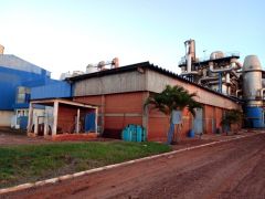 SUGAR AND ALCOHOL PLANTREFERENCE NUMBER: A-2511 SUGAR AND ALCOHOL PLANT CANE UNLOAD SECTOR THE CANE UNLOADING SECTOR IS EQUIPPED WITH THE EQUIPMENT LISTED BELOW IN THE CONDITION TO CARRY OUT A GRINDING OF 8400 TCD WHICH CORRESPONDS TO A HARVEST OF 1800000 TONNES OF CANE / YEAR • 01 HILO UNLOADER OF STORAGE • 01 HILO UNLOADER OF MILLING • 01 FEEDER SUGARCANE TABLE WITH INCLINATION OF 25 INCHES • 01 FEEDER SUGARCANE TABLE WITH INCLINATION OF 45 INCHES • 02 CRANES WITH CAPACITY OF 20 TONNES • 01 TRANSPORTER TYPE CUSCH - CUSH OF 40 INCHES • 02 MOTOR PUMP WITH CAPACITY OF 1000 M³/H TO 50 MCW FOR CANE WASHING • 01 CONTAMINATED FLUID TREATMENT SYSTEM • 01 METAL STRUCTURE BUILDING MEASURING 20000 X 100000 mm CANE PREPARATION SECTOR THE SUGARCANE PREPARATION SECTOR IS EQUIPPED WITH THE FOLLOWING AUTOMATED EQUIPMENT WITH THE CONTROL BY THE SUPERVISORY INSTALLED IN THE CONTROL ROOM AS SHOWN BELOW TO PERFORM A CRUSHING OF 7200 TCD WHICH CORRESPONDS TO A CROP OF 1600000 TONS OF SUGARCANE / YEAR • 01 METALLIC CONVEYOR OF 60 INCHES • 01 LEVELING OF CANE OF 60 INCHES • 01 CANE KNIVES SET TYPE COP-8 OF 60 INCHES • 01 CAN SHREDDER SET TYPE COP-5 OF 60 INCHES • 01 FEEDER ROLL 60 IINCHES • 01 RUBBER TRANSPORTER FOR CANE SHREDDED OF 60 INCHES • 01 TGM TURBINE FOR KNIVES SET • 01 TGM TURBINE FOR SHREDDER SET • 01 HIGH AND LOWER SPEED REDUCER OF KNIVES SET • 01 HIGH AND LOWER SPEED REDUCER OF SHREDDER SET • 01 REDUCER FOR METALLIC CONVEYOR • 01 REDUCER FOR FEEDER ROLL • 01 REDUCER OF SHREDDED CANE TRANSPORTER TYPE BELT MILLING CANE SECTOR THE CANE MILLING SECTOR OF THE PLANT IS EQUIPPED WITH THE FOLLOWING AUTOMATED EQUIPMENT WITH THE CONTROL BY THE SUPERVISORY INSTALLED IN THE CONTROL ROOM TO CARRY OUT A GRINDING OF 7200 TCD CORRESPONDING TO A 222 - DAY HARVEST TO GRIND 1600000 TONS. CANE / YEAR • 04 MILLS OF 32 X 60 INCHES • 03 INTERMIDIATE TRANSPORTER OF 60 INCHES • 01 ROTARY SIEVE FOR MILLING 300 TCD • 01 TGM TURBINE OF DRIVING THE 1º / 2º MILLS • 01 TGM TURBINE OF DRIVING OF 3º / 4º MILLS • 01 REDUCER OF HIGH AND LOW SPEED OF DRIVING THE 1º / 2º MILLS • 01 REDUCER OF HIGH AND LOW SPEED OF DRIVING THE 3º / 4º MILLS • 03 REDUCER INTERMEDIATE TRANSPORTER OF 60 INCHES • 02 PUMPS OF 1ST JUICE • 02 PUMPS OF JUICE IMBIBITION OF 3RD FOR 2ND MILL • 02 PUMPS OF JUICE IMBIBITION OF 4TH FOR 3RD MILLS • 02 PUMPS OF MIXED JUICE OF MILL FOR JUICE TREATMENT STEAM GENERATION SECTOR THE STEAM GENERATION SECTOR OF THE PLANT IS PREPARED TODAY TO PERFORM A 7200 TCD GRINDING CORRESPONDING TO A 220 - DAY HARVEST TO GRIND 1600000 TON. CANE / YEAR WITH THE FOLLOWING AUTOMATED EQUIPMENT WITH CONTROL BY THE SUPERVISORY INSTALLED IN THE CONTROL ROOM AS SHOWN BELOW • 01 BOILER N ° 01, MODEL: TS-3-150 MODIFIED FOR CBS-120-21 KG / CM² TODAY GENERATES AN AVERAGE OF 11000 KG / HR OF STEAM AT A PRESSURE OF 21 KG / CM² • 01 BOILER N ° 02, MODEL: TS-3-150-21 KG / CM² TODAY GENERATES AN AVERAGE OF 55000 KG / HR OF STEAM AT A PRESSURE OF 21 KG / CM² • 01 DEAERATOR WITH A CAPACITY OF 70 M³ • 01 78 INCHES BAGASSE METALLIC TRANSPORTER OF 32000 mm LENGTH • 01 48 INCHES BAGASSE TRANSPORTER FROM MILL TO BOILER • 01 48 INCHES BAGASSE RETURN TRANSPORTER FOR BOILER • 01 REDUCER OF BAGASSE TRANSPORTER FROM MILL TOBOILER • 01 REDUCER OF BAGASSE RETURN TRANSPORTER TOBOILER • 02 MOTO - PUMPS OF WATER FEEDING OF DEAERATOR • 02 MOTO - PUMPS OF WATER TREATMENT OF BOILER • 01 MOTO - PUMP WITH CAPACITY OF 300 M³/H TO 350 MCW FOR WATER FEEDING OF BOILER • 01 TURBO-PUMP WITH CAPACITY OF 300 M³/H TO 350 MCW FOR WATER FEEDING OF BOILER • 02 MOTO-PUMPS WITH CAPACITY OF 220 M³/H TO 50 MCW FOR WET SCRUBBER OF BOILER NO. 2 • 03 MOTO - PUMPS OF 40 M³/H TO 300 MCW • 01 METALLIC RESERVOIR WITH 200 M³ OF CONDENSED WATER CAPACITY POWER GENERATION SECTOR THE POWER GENERATION SECTOR IS EQUIPPED WITH THE FOLLOWING MODERN AND AUTOMATED EQUIPMENT LISTED BELOW TO MEET A GRINDING OF 8400 TCD • 01 THREE - PHASE GENERATOR OF 6250 KVA – 13800 VOLTS – 60Hz • 01 TGM STEAM TURBINE MODEL TM - 5000 • 01 REDUCER RENK - ZANINI WITH CAPACITY OF 5000 KW • SEVERAL ELECTRICALS PANELS OF THE GENERATOR • 01 TURBO GENERATOR HOUSE BUILDING • 02 WATER COOLING TOWERS FOR THE TURBO-GENERATOR • 02 MOTO - PUMPS OF 100 M³/H TO 30 MCW SUGAR FACTORY THE SUGAR FACTORY WAS SET UP BETWEEN 2007 / 2008 AND COMPLETELY AUTOMATED WITH THE CONTROL BY THE SUPERVISORY INSTALLED IN THE CONTROL ROOM, PRODUCING AN AVERAGE OF 500000 KG OF VHP SUGAR PER DAY, A VALUE CORRESPONDING TO A MILLING OF 5000 TCD. THE TRANSPORT OF THIS SUGAR MANUFACTURED AT THE DECASA PLANT IS BEING TRANSPORTED BY MEANS OF A BUCKET VEHICLE WITH A DESTINATION INFORMED BY THE CUSTOMER. FOR THIS PLANT TO PRODUCE CRYSTAL SUGAR IC - 150, WE WILL NEED TO ACQUIRE AND ASSEMBLE THE FOLLOWING EQUIPMENT • SULFITATION EQUIPAMENT • BAGGING EQUIPMENT OF 50 KG BAGS • BUILD OR RENT AN INFLATABLE WAREHOUSE TO STORE SUGAR WITH THE INSTALLATION OF THIS EQUIPMENT, THE SUGAR FACTORY IS PREPARED TO RECEIVE A MILLING OF 5000 TCD CORRESPONDING TO A DAILY PRODUCTION OF 500000 KG OF CRYSTAL SUGAR IC - 150 PER DAY ALCOHOL DISTILLERY THE DISTILLERY WAS INSTALLED IN 1982 WITH A CAPACITY OF 300000 LITERS OF HYDRATED ALCOHOL PER DAY. WHEN THE FORMER OWNER'S UNIT WAS SOLD TO THE OLIVAL TENÓRIO GROUP IN 2003, THE NEW ENTREPRENEUR INVESTED IN THE MANUFACTURE OF ALCOHOL IN 2006 BY INSTALLING ANOTHER COLUMN OF DISTILLATION WITH A CAPACITY OF 300,000 LITERS AND AUTOMATED 100% INCREASING ITS PRODUCTION CAPACITY TO 600,000 LITERS OF HYDRATED ALCOHOL PER DAY • 02 TYPE “A” DISTILLATION COLUMNS WITH CAPACITY TO PRODUCE 300 M³ OF ALCOHOL / DAY • 02 TYPE “B” RECTIFICATION COLUMNS WITH CAPACITY FOR PRODUCTION OF 300 M³ OF ALCOHOL / DAY • 01 TYPE “A” DISTILLATION COLUMN WITH CAPACITY FOR PRODUCTION OF 300 M³ OF ALCOHOL / DAY • 01 TYPE “B” RECTIFICATION COLUMN WITH CAPACITY FOR PRODUCTION OF 300 M³ OF ALCOHOL / DAY • 09 TUBULAR HEAT EXCHANGERS TYPE “K” • 02 TUBULAR HEAT EXCHANGERS TYPE “J” • 02 TUBULAR HEAT EXCHANGERS TYPE “E” • 02 TUBULAR HEAT EXCHANGERS TYPE “E1” • 02 TUBULAR HEAT EXCHANGERS TYPE “E2” • 02 TUBULAR HEAT EXCHANGERS TYPE “R” • 02 TUBULAR HEAT EXCHANGERS TYPE “R1” • 11 NEW FERMENTATION VATS WITH A CAPACITY OF 300 M³ • 03 PLATE HEAT EXCHANGERS FOR THE WORT • 05 PLATE TYPE HEAT EXCHANGERS FOR VATS • 01 VAT FOR WINE • 01 CO₂ RECOVERY COLUMN • 02 PUMPS WITH A CAPACITY OF 600 M³ / H - 50 MCA FOR THE COOLING SYSTEM OF THE PLATE HEAT EXCHANGERS • 01 PUMP WITH A CAPACITY OF 800 M³ / H FOR THE COOLING SYSTEM OF THE PLATE HEAT EXCHANGERS • 02 CENTRÍFUGES HAD - 90 • 04 CENTRÍFUGES HAD - 60 WITH THE INSTALLATION OF THIS EQUIPMENT, THE ALCOHOL DISTILLERY IS PREPARED TO PRODUCE 600000 LITERS OF ALCOHOL PER DAY, RECEIVING A MILLING OF 6500 TCD CORRESPONDING TO 2500000 TONS OF CANE / YEAR Learn More
 -
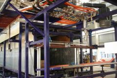 E-9384 HORIZONTAL AUTOMATIC CONTINUOUS FOAMING LINEINVENTORY NUMBER: E-9384 HORIZONTAL AUTOMATIC CONTINUOUS FOAMING LINE OVEN LENGTH: 16.9 M. FOAMING HEIGHT: 1.0 TO 1.3 M. FOAMING WIDTH: 1.15 TO 2.3 M. FOAMING DENSITY: 10 TO 50KG/M3. CONVEYOR BELT LENGTH: 16.9 M. SIDE BOARD WIDTH ADJUSTMENT: 0.98 TO 2.4M. CONVEYOR BELT SPEED: 2.0 TO 7.0M/MIN. MIXING-HEAD POWER: 37KW. WITH BLOCK CUTTING MACHINE. TOTAL POWER: 130KW. TOTAL OUTPUT: 200 TO 350KG/MIN. MACHINE EXTERNAL SIZE: L34000 X W4550 X H4200mm. CE CERTIFICATE GUARANTEE FOR ONE YEAR. QUANTITY AVAILABLE: 1 Learn More
 -
 M-0428 CATTLE SLAUGHTERING AND PROCESSING EQUIPMENT FOR 200 CATTLES PER DAYREFERENCE NUMBER: M-0428-SHORT VERSION CATTLE SLAUGHTERING AND PROCESSING EQUIPMENT FOR 200 CATTLES PER DAY 200 CATTLES PER DAY QUANTITY AVAILABLE: 1 Learn More
 -
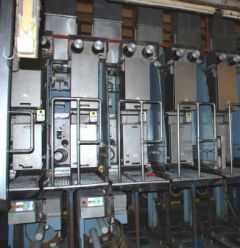 G-0784 RIETER FDY EXTRUSION EQUIPMENT FOR POLYPROPYLENE YEAR 1996/98
REFERENCE NUMBER: G-0784
RIETER FDY EXTRUSION EQUIPMENT FOR POLYPROPYLENE YEAR 1996/98
1. Machine m26/39:
Year 1996
For 1 fdy spinning line with 2+4 positions, each position with 4 ends
Product: fdy-yarn on bobbins
Raw material: pp, dried filament grade chips
Yarn count range: 150 – 400 dtex
Winder speed for target: 4000 m/min
Machine technical data:
Position gauge: 800 mm
Spinning pump capacity: 4x10 ccm/rev
Spinneret size diameter: 95 mm
Quench width: 670 mm
Quench length: 1700 mm
Number of spin-finish pumps per position: 1
Capacity of spin-finish pump: 4x0.05 ccm/rev
Number of winders/position: 1
Type of winder: riemat a6-094
Number of packages/winder: 4
Maximum package diameter: 420 mm
Package stroke: 190 mm
Package weight at 280 mm package diameter: approx. 6.2 kg
Detailed technical specifications:
Extruder for 4 positions Year 1998:
1 extruder type e1. 105-30m:
-nominal extruder capacity: max 275 kg/h for pp
-operational extruder capacity: max 248 kg/h for pp
-screw diameter: 105 mm
-l/d ratio: 30
-barrel with:
electrical ceramic heaters
7 heating zones, each zone equipped with one 2xpt100
heating zone capacity approx. 58 kw
inlet zone, water cooled
nozzle for nitrogen purge
insulation
-screw with torpedo mixing head
-reduction gear, including belt transmission to motor
-dc motor, rated power approx. 95kw
-extruder frame
1 extruder measuring head, dowtherm vapour heated
-measuring head comprising:
coarse filter
insulation
-double pt100, one each for melt and dowtherm vapour temperature
-pressure sensors for melt pressure, one in front and one behind the coarse filter
1 melt distribution system, dowtherm vapour heated
-melt distribution system comprising
main product pipe between extruder, measuring head and melt distributor.
Extruder for 2 positions Year 1998:
1 extruder type e1. 60-30
-nominal extruder capacity: max 275 kg/h for pp
-operational extruder capacity: max 248 kg/h for pp
-screw diameter: 60 mm
-l/d ratio: 30
-barrel with
electrical ceramic heaters
6 heating zones, each zone equipped with one 2xpt100
heating zone capacity approx. 17 kw
inlet zone, water cooled
insulation
-screw nitrited with maddock mixing head
-reduction gear, including belt transmission to motor
-dc motor, rated power approx. 22kw
-extruder frame
1 extruder measuring head, electrically heated year 1998
-measuring head comprising:
insulation
Double pt100, one each for melt and dowtherm vapour temperature
pressure sensors for melt pressure
burst disc for power switch-off at overpressure.
1 melt distribution system, dowtherm vapour heated
-melt distribution system comprising
main product pipe between extruder, measuring head and melt distributor.
1 riebeam bottom loading spinning beam year 1998
-beam comprising:
welded-in pump blocks with bolted pump adapter plate
silumin insulation blocks
melt distribution pipes with polished inner surfaces
efficient vapour heating on all sides of spin pumps
optimized heat condustion to the spinnerets
1 freezing valve upstream of each spinpump
2 pressure sensors for measuring the melt pressure in front and behind the spinpump
(2 per line)
heating box, completely insulated
heating by dowtherm vapour
1 double pt100 for measuring and controlling the heating box temperature
Designed as follows:
-bottom loading of rieter quickfit spinpacks
-design temperature 320°c
-maximum allowable working pressure: 300 bar for melt pipe and 2.57 bar for jacket
Dowtherm evaporator and components for heating system:
-electrically heated, total capacity approx 25 kw
-shut-off valves
-drainage valves
-dry protection sensor
-magnetic controlled level gauge
- vent system on top of measuring head.
Poy spin packs, type rieter quickfit:
-max pressure in the spinpack: 350 bar
-design temperature: 320 °c
-spinneret outside dimensions: 95 mm
-bottom loading design
-bayonet locking, insert and tighten by turning 90°
-self sealing system
-sand or metal powder filtration, 3 cm filling depth
-wire mesh filters
Spin pumps with motors and gears:
Gear pumps, 4-fold
Capacity 4 x 6 ccm/rev
Each spin pump system comprising
Individual drive motor with flange connection to the reduction gear
Hollow gear shaft for installation of spin pump shaft
Shaft with shear pin protection
Reduction ratio 1:80
Pump speed: 8-30 rev/min
Motor type: synchronous ac-motor
Rated power: 500w at 50 cps
Quench air cabinets bsk 670/1700:
Each cabinet comprising:
-rigid cabinet made from welded sheet metal, painted, side walls made from alu sheet metal
-air rectifier consisting of different layers of perforated metal sheets, rectifiers removable to the front for cleaning.
-1 perforated hinged door
-air inlet duct flanged with counter flange, comprising air flow regulating flaps
-interfloor filament duct, length 2000 mm
-alu chutes for start-up
-nozzles for connection of differential pressure gauge.
Spinning vapour exhausts:
-exhaust hood per spinning position for removal of spinning vapour
-hood designed as follows:
made from stainless steel
air flow regulation flap
hood removable for cleaning
Take-up frames, type riedraw 1:
Welded steel frame, housing all drawrolls, compressed air supply pipes for the aspirator units and the yarn waste pipes within the fdy take-up unit.
Per position:
4 inlet yarn guides
4 spin finish application nozzles
1 yarn cutter / aspirator unit
1 spin finish pump
4 centring yarn guides
4 intermingling units
rolls as described further
1 automatic winder riemat a6-094
Drawrolls year 1998:
Mono 1 with 1 rievap 32 dual shell drawroll, type j7/32-40, ot40
Speed range: 750 to 4000 mpm
Roll diameter: 190 mm
Working width: 250 mm
Temperature range: 45-250°c
And 1 bearing separator roll, type srd60 hard chromium plated
Duo 1 with 2 rievap 32 dual shell drawroll, type j7/32-60, ot40
Speedrange: 1000 to 6000 mpm
Roll diameter: 190 mm
Working width: 250 mm
Temperature range: 45-250°c
Duo 2 with 2 rievap 32 dual shell drawroll, type j7/32-60, ot40
Speedrange: 1000 to 6000 mpm
Roll diameter: 190 mm
Working width: 250 mm
Temperature range: 45-250°c
Duo 3 with 2 cold draw roll units each type j7/45-55
Speedrange: 1800 to 5500 mpm
Roll diameter: 150 mm
Working width: 180 mm
Automatic and wasteless winder riemat a6-094
Spindle driven
Number of ends per winder: 4 ends
Yarn count range: 15 to 1000 dtex
Take up speed: 2500 to 5500 m/min
Chuck length: 900 mm
190 mm stroke, 420 mm outside package diameter
Package volume: 24.7 dm³
Tube bore: 94 ±0.2 mm
Tube outside diameter: 106 ±0.4 mm
Tube length: 225 ±0.5 mm
Oil-mist lubrication unit:
Compressed air distribution station
Mobile aspirator guns with hoses
Electrical control equipment
-for electrical power
general: 3 x 380v/50hz plus ground wire
euro-standard: 3x400v 50 or 60hz plus ground wire
maximum voltage variation ±10% measured at terminals of cabinets
maximum frequency variation: ±2%
Process control system (cif):
fully integrated control system to control and monitor the entire spinning line.
the central monitoring unit si linked to the plc of the spinning section and the plcs of each spinning position.
Drive and heater control year 1998:
Spinning section:
Speed adjustment for the extruder motor is done via a dc-convertor
To achieve a constant pressure at the extruder outlet, the output of the pressure controller is transmitted to the dc-converter to adjust the extruder speed.
The feedback of the actual extruder speed is done by a tacho generator mounted on the extruder motor.
One common frequency inverter supplies the synchronous ac motors for the spin pumps.
According to process conditions, the plc transmits the setpoint to the inverter.
All motors are equipped with an overload protection.
Solid state relays heat each extruder zone and spinning beam.
Each extruder zone and the spinning beam represent an independent control loop.
Take-up section:
The inverter unit is a processor-controlled static frequency inverter for powering the 3-phase motors.
All inverter units in a position cabinet are supplied with approx 570v dc from a common rectifier.
Heating system:
The heating unit rhu is processor-controlled.
The power supply is taken straight from 3-phase 380/400v which powers the cabinet.
The inductor is fitted inside the draw roll.
The rhu switches the current on and off in this inductor. While current flows, a voltage is inducted into the
Rotating draw roll.
This sets up a short-circuit current in the draw roll, thereby heating the roll unit.
2. Machines m27/ 28 / 30 year 1998:
For 3 fdy spinning lines each with 2 positions, and each position with 4 ends
Product: fdy-yarn on bobbins
Raw material: pp, dried filament grade chips
Yarn count range: 150 – 400 dtex
Winder speed for target: 4000 m/min
Machine technical data:
Position gauge: 1000 mm
Spinning pump capacity: 4x7.5 ccm/rev
Spinneret size diameter: 95 mm
Quench width: 470 mm
Quench length: 1200 mm
Number of spin-finish pumps per position: 2
Capacity of spin-finish pump: 4x0.16 ccm/rev + 4x0,05 ccm/rev
Number of winders/position: 1
Type of winder: riemat a6-094
Number of packages/winder: 4
Maximum package diameter: 420 mm
Package stroke: 190 mm
Package weight at 280 mm package diameter: approx. 6.2 kg
Detailed technical specifications:
1 extruder type e1. 60-30m
-nominal extruder capacity: max 80 kg/h for pp
-screw diameter: 65 mm
-l/d ratio: 30
-barrel with:
electrical ceramic heaters
7 heating zones, each zone equipped with one 2xpt100
heating zone capacity approx. 22 kw
inlet zone, water cooled
nozzle for nitrogen purge
insulation
-screw with torpedo mixing head
-reduction gear, including belt transmission to motor
-dc motor, rated power approx. 22kw
-extruder frame
1 extruder measuring head, electrically heated:
-measuring head comprising:
coarse filter
insulation
-double pt100, one each for melt and dowtherm vapour temperature
-pressure sensors for melt pressure, one in front and one behind the coarse filter
1 melt distribution system, dowtherm vapour heated:
Melt distribution system comprising:
main product pipe between extruder, measuring head and melt distributor.
1 riebeam bottom loading spinning beam:
-beam comprising:
welded-in pump blocks with bolted pump adapter plate
silumin insulation blocks
melt distribution pipes with polished inner surfaces
efficient vapour heating on all sides of spin pumps
optimized heat condustion to the spinnerets
1 freezing valve upstream of each spinpump
2 pressure sensors for measuring the melt pressure in front and behind the spinpump
(2 per line)
heating box, completely insulated
heating by dowtherm vapour
1 double pt100 for measuring and controlling the heating box temperature
Designed as follows:
-bottom loading of rieter quickfit spinpacks
-design temperature 320°c
-maximum allowable working pressure: 300 bar for melt pipe and 2.57 bar for jacket
Dowtherm evaporator and components for heating system:
-electrically heated, total capacity approx 18 kw
-shut-off valves
-drainage valves
-dry protection sensor
-magnetic controlled
-level gauge
-vent system on top of measuring head.
Poy spin packs, type rieter quickfit:
Max pressure in the spinpack: 350 bar
Design temperature: 320 °c
Spinneret outside dimensions: 95 mm
Bottom loading design
Bayonet locking, insert and tighten by turning 90°
Self sealing system
Sand or metal powder filtration, 3 cm filling depth
Wire mesh filters
Spin pumps with motors and gears:
Gear pumps, 4-fold
Capacity 4 x 7.5 ccm/rev
Each spin pump system comprising
individual drive motor with flange connection to the reduction gear
hollow gear shaft for installation of spin pump shaft
shaft with shear pin protection
reduction ratio: 1:80
pump speed: 8-30 rev/min
motor type: synchronous ac-motor
rated power: 500w at 50 cps
Quench air cabinets bsk 470/1200
Each cabinet comprising:
-rigid cabinet made from welded sheet metal, painted, side walls made from alu sheet metal
-air rectifier consisting of different layers of perforated metal sheets, rectifiers removable to the front for cleaning.
-1 perforated hinged door
-air inlet duct flanged with counter flange, comprising air flow regulating flaps
-interfloor filament duct, length 2000 mm
-alu chutes for start-up
-nozzles for connection of differential pressure gauge.
Spinning vapour exhausts:
-exhaust hood per spinning position for removal of spinning vapour
-hood designed as follows:
made from stainless steel
air flow regulation flap
hood removable for cleaning
Take-up frames, type riedraw 1:
Welded steel frame, housing all drawrolls, compressed air supply pipes for the aspirator units and the yarn waste pipes within the fdy take-up unit.
Per position:
4 inlet yarn guides
2 spin finish application nozzles per end
1 yarn cutter / aspirator unit
2 spin finish pump
4 centring yarn guides
4 pre-intermingling jets
4 intermingling units
1 additional operator panel between duo1 and duo 2.
rolls as described further
1 automatic winder riemat a6-094
Drawrolls:
Mono 1 with 1 rievap 32 dual shell drawroll, type j7/32-40, ot40
Speedrange: 750 to 4000 mpm
Roll diameter: 190 mm
Working width: 250 mm
Temperature range: 45-250°c
And 1 bearing separator roll, type srd60
Hard chromium plated
Duo 1 with 2 rievap 32 dual shell drawroll, type j7/32-60, ot40
Speedrange: 1000 to 6000 mpm
Roll diameter: 190 mm
Working width: 250 mm
Temperature range: 45-250°c
Duo 2 with 2 rievap 32 dual shell drawroll, type j7/32-60, ot40
Speedrange: 1000 to 6000 mpm
Roll diameter: 190 mm
Working width: 250 mm
Temperature range: 45-250°c
Duo 3 with 2 cold draw roll units each type j7/45-55
Speedrange: 1800 to 5500 mpm
Roll diameter: 150 mm
Working width: 180 mm
Automatic and wasteless winder riemat a6-094:
Spindle driven
Number of ends per winder: 4 ends
Yarn count range: 15 to 1000 dtex
Take up speed: 2500 to 5500 m/min
Chuck length: 900 mm
190 mm stroke, 420 mm outside package diameter
Package volume: 24.7 dm³
Tube bore: 94 ± 0.2 mm
Tube outside diameter: 106 ± 0.4 mm
Tube length: 225 ± 0.5 mm
Compressed air distribution station:
Mobile aspirator guns with hoses
Electrical control equipment
For electrical power
general : 3 x 380v/50hz plus ground wire
Euro-standard: 3x400v 50 or 60hz plus ground wire
Maximum voltage variation ±10% measured at terminals of cabinets
maximum frequency variation: ±2%
Process control system (cif):
Fully integrated control system to control and monitor the entire spinning line.
The central monitoring unit si linked to the plc of the spinning section and the plcs of each spinning position.
Drive and heater control:
Spinning section.
Speed adjustment for the extruder motor is done via a dc-convertor.
To achieve a constant pressure at the extruder outlet, the output of the pressure controller is transmitted to the dc-converter to adjust the extruder speed.
The feedback of the actual extruder speed is done by a tacho generator mounted on the extruder motor.
One common frequency inverter supplies the synchronous ac motors for the spin pumps.
According to process conditions, the plc transmits the setpoint to the inverter.
All motors are equipped with an overload protection.
Solid state relays heat each extruder zone and spinning beam.
Each extruder zone and the spinning beam represent an independent control loop.
Take-up section:
The inverter unit is a processor-controlled static frequency inverter for powering the 3-phase motors.
All inverter units in a position cabinet are supplied with approx 570v dc from a common rectifier.
Heating system:
The heating unit rhu is processor-controlled.
The power supply is taken straight from 3-phase 380/400v which powers the cabinet.
The inductor is fitted inside the draw roll.
The rhu switches the current on and off in this inductor.
While current flows, a voltage is inducted into the rotating draw roll.
This sets up a short-circuit current in the draw roll, thereby heating the roll unit.
HOURLY PRODUCTION:
FOR 150 DENIER @ 3500 MPM WINDER SPEED, THE HOURLY PRODUCTION IS 3.5 KG/BOBBIN.
AS THERE IS 4 ENDS PER POSITION, THIS MEANS 14 KG/HOUR/POSITION
M26/39 ARE OF 2 + 4 POSITIONS; HENCE M26 = 28 KG/HOUR AND M39 = 56 KG/HOUR
M27/28/30 ARE OF 2 POSITIONS EACH, HENCE 28 KG/HOUR EACH.
(AS PER OUR PEOPLE AT THE EXTRUSION PLANT, THEY WERE RUNNING TRIALS TO PRODUCE THE 150 DENIER @ 4000 MPM WINDER SPEED)
FOR 300 DENIER @ 3600 MPM WINDER SPEED, THE HOURLY PRODUCTION IS 7.2 KG/BOBBIN.
AS THERE IS 4 ENDS PER POSITION, THIS MEANS 28.8 KG/HOUR/POSITION
M26/39 ARE OF 2 + 4 POSITIONS; HENCE M26 = 57.6 KG/HOUR AND M39 = 115.2 KG/HOUR
M27/28/30 ARE OF 2 POSITIONS EACH, HENCE 57.6 KG/HOUR EACH.
FOR 600 DENIER @ 2200 MPM WINDER SPEED, (SPEED LIMITATION DUE TO EXTRUDER CAPACITY) THE HOURLY PRODUCTION IS 8.8 KG/BOBBIN.
AS THERE IS 4 ENDS PER POSITION, THIS MEANS 35.2 KG/HOUR/POSITION
M26/39 ARE OF 2 + 4 POSITIONS; HENCE M26 = 70.4 KG/HOUR AND M39 = 140.8 KG/HOUR
M27/28/30 ARE OF 2 POSITIONS EACH, HENCE 70.4 KG/HOUR EACH.
MACHINE HAS BEEN PARTIALLY DISASSEMBLED (EXTRUDERS AND SPINBEAMS HAVE BEEN TAKEN DOWN TO GROUNDFLOOR) REST OF THE EQUIPMENT STILL TO BE DISASSEMBLED
Learn More -
 YY-1481 FULL-AUTOMATIC FOLDING MACHINE OF 4-PLY LAP FOAM, 15 PIECES PER MINUTEYY-1481 FULL-AUTOMATIC FOLDING MACHINE OF 4-PLY LAP FOAM, 15 PIECES PER MINUTE FEATURE: - USED FOR FULL-AUTOMATIC FOLDING OF SURGICAL TOWEL, LAP FOAM AND ABDOMINAL TOWEL. - GAUZE ROLL RUNNING ON THE EQUIPMENT WHICH IS AUTOMATICALLY FEEDING, CUTTING, HEMMING, PRESSING, FOLDING AND YARD OPERATING NEATLY. - EQUIPPED WITH 5-6 CNC MOTORS, THE PARAMETER CAN BE MODIFIED IN THE MAN-MACHINE INTERFACE, WHICH WILL BE VERY CONVENIENT TO CHANGE THE PRODUCT VARIETY. - FURTHERMORE, IT CONFIGURES AUTOMATIC DISCHARGING MACHINE, WHICH WITH HIGHER DEGREE OF AUTOMATION, DISCHARGING RESET AUTOMATICALLY AFTER THE OPERATION. - ADVANTAGES OF FULL-AUTOMATIC FOLDING MACHINE: FIRSTLY, THE PRODUCT SIZE IS ACCURATE AND APPEARANCE TIDY. SECONDLY, MACHINE FOLDING TO REDUCE THE SECONDARY POLLUTION, IMPROVE THE PRODUCT QUALITY. AT LAST, IT CAN SHARPLY REDUCE THE LABOR COST, THE INVESTMENT COSTS WILL BE RECOVERED IN HALF YEAR. Learn More
 -
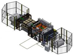 NANOSPIDER - ELECTROSPINREFERENCE NUMBER: A-2510 NANOSPIDER - ELECTROSPIN FIRST – (ROUNDED TANKS) NEW GENERATION NS PRODUCTION LINE ALLOWS NANOFIBERS TO BE PRODUCED ON A FULLY-INDUSTRIAL SCALE FOR A NUMBER OF APPLICATIONS FEATURES: • CONSTRUCTION USING SELF - EXTINGUISHING MATERIALS • VENTILATED SPINNING CHAMBER, PREVENTING THE ESCAPE OF SOLVENT FUMES • GROUNDING ROD FOR CHARGE DISSIPATION AND AUTOMATIC GROUNDING SYSTEM • FOUR EMERGENCY - STOP BUTTONS ARE PLACED ON THE CORNERS OF THE UNIT • ONE EMERGENCY - STOP BUTTON IS PLACED ON THE SERVICE CONTROL PANEL • THE TWO UPWARD SLIDING DOORS ARE EQUIPPED WITH AUTOMATIC DOOR LOCKS WITH LIMIT SWITCHES TO PREVENT ACCIDENTAL OPENING AND WILL ALSO SHUT DOWN THE UNIT IF A SLIDING DOOR IS ACCIDENTALLY OPENED • THE FOUR LOWER SWING OPEN DOORS HAVE LIMIT SWITCHES THAT WILL SHUT DOWN THE UNIT IF THE DOOR IS ACCIDENTALLY OPENED • FIRE SUPPRESSION SYSTEM FOR THE SPINNING CHAMBER WITH MANUAL ACTIVATION VIA BUTTON ON THE CONTROL PANELS • THE EQUIPMENT IS PRODUCED ACCORDING TO CE STANDARDS • RECOMMENDED ROOM LAYOUT: THE LAYOUT WILL BE OPTIMIZED ACCORDING TO BUYER NEEDS • LIGHTS ON THE FRONT AND BACK OF MACHINE SPECIFICATIONS: POLYMER (PROCESS) TANKS COMPONENT IS CONSISTING FROM FOLLOWING PARTS • CYLINDRICAL TANKS ON WHEELS, ONE FOR FRESH POLYMER • CYLINDRICAL TANKS ON WHEELS, ONE FOR WASTE • MIXING CAPABILITY (PNEUMATIC MIXTURE) FOR IN AND OUT TANKS - PNEUMATIC DRIVEN AGITATOR • CLEANING SHOWER FOR BOTH IN AND OUT TANK • TWO CYLINDRICAL SHAPED TANKS ON THE WHEELS IN ONE TUB • BURST DISK FOR EACH TANK • QUICK COUPLINGS STÄUBLI HCB 08 WORKING VOLUME OF TANKS IS 60 LITERS FOR EACH TANK CLEANING TANKS COMPONENT IS CONSISTING FROM FOLLOWING PARTS • TANK WITH VOLUME OF 60 LITERS WILL BE DIVIDED INTO TWO SECTIONS: 30 L FOR CLEAN,30 L USED CLEANING SOLUTION • CYLINDRICAL TANK ON WHEELS - SIZE ROUGHLY HALF OF THE PROCESS TANKS • BURST DISK FOR EACH TANK VOLUME 30 + 30 LITERS WILL BE POSSIBLE TO USE MULTIPLE TIMES FOR CLEANING SITE PREPARATION / CONNECTION REQUIREMENTS ALL POWER SUPPLY IS REALIZED FOR FULL LINE INCLUDING PERIPHERAL PARTS. IT IS JUST NECESSARY TO CALCULATE INCREASE OF ELECTRICAL POWER, SPACE AND AIR FLOW VOLTAGE: 220 VOLTZ AND 50/60Hz, MAIN CIRCUIT BREAKER 32 A POWER CONSUMPTION: UP TO 12 KW PRESSURE AIR: 5 TO 8 BAR, CONNECTION POINT CAPACITY 1000 L/min INERT GAS: 0.5 BAR, CONNECTION POINT CAPACITY 200 L/min PROCESS AIR INLET/OUTLET: UP TO 1000 M3/H PRODUCT SIZE AND WEIGHT LENGTH: APPROX. 2800 mm WIDTH: APPROX. 3300 mm HEIGHT: APPROX. 3000 mm WEIGHT: APPROX. 2500 KG SCOPE OF SUPPLY SPINNING CHAMBER • WITH WIRE COLLECTING ELECTRODE • LIFTING MECHANISM OF CART CAPABLE OF ADJUSTING THE DISTANCE BETWEEN THE COLLECTING AND SPINNING ELECTRODE BETWEEN 150 AND 250 mm VIA THE CONTROL PANEL • HV PROTECTING COVERS • SLIDING DOORS WITH ILLUMINATION • AIR INLET AND OUTLET WITH HOMOGENIZER AND FANS EXTINGUISHING SYSTEM • SWITCHBOARD SPINNING CART • 2 X PROCESS DOUBLE - TANKS (ONE CART ON WHEEL, EACH WITH IN AND OUT TANK) • CDS – CHEMICAL DISTRIBUTION SYSTEM • SEPARATE SPINNING MODULE EACH WITH MOVABLE CARRIAGE WITH SPINNING HEAD, ENERGY CHAIN • HV COVERS • WIRE SPINNING MECHANISM • WIRE ALIGNMENT MECHANISM • SET OF WIRE SPOOL 0.2 mm AND 0.3 mm MAIN OPERATOR PANEL – CONTROL SYSTEM HV POWER SUPPLIES SYSTEM (MAXIMUM AVAILABLE RATINGS + 80 KV DC / - 60 KV DC) SET OF SPINNING NOTCHES – FOR ROR 1 X CLEANING TANKS SERVICE OPERATION PANEL AUTOMATIC DISCHARGER R & D MODE ENABLE ELECTRO SPINNING FROM 4 WIRES ONLY – ONE MODULE PREPARATION FOR DRIVEN ENDLESS BELT COLLECTING ELECTRODE NOT IN SCOPE OF SUPPLY • SPARE WIRE FOR SPINNING • SPARE POLYMER CONTACT COMPONENT: CDS (PUMPS, VALVES, HOSES), SPINNING CARRIAGES WITH SPINNING HEADS, ENERGY CHAINS WITH POLYMER HOSES • SET OF SPINNING NOTCHES – NOT NECESSARY FOR ROR • ENDLESS BELT COLLECTING ELECTRODE REWINDING 1600 mm FULL THE NS LINE ALLOWS THE PRODUCTION OF NANOFIBERS ON A SUBSTRATE MATERIAL ONLY. THE SUBSTRATE MATERIAL MUST BE PRESENT IN THE SPINNING UNIT DURING THE SPINNING PROCESS. MOST NANOFIBER PRODUCTS USE TEXTILE, PAPER, OR FOIL SHEETS IN ROLLS AS A SUBSTRATE MATERIAL. UNWIND AND REWIND EQUIPMENT ALLOWS BIDIRECTIONAL REWINDING OF THE SUBSTRATE MATERIAL. THE ROLL GOODS EXCHANGE AND INSERTION IS MANUAL. MANIPULATION TOOLS ARE USUALLY NECESSARY BOTH UNWIND AND REWIND CONTAINS STEEL FRAMES WITH MOTORS, WHICH DRIVE THE UNWINDING AND WINDING PNEUMATIC SHAFTS SPEED IS CONTROLLED BY A SPECIAL RUBBER CYLINDER. THE PNEUMATIC SHAFTS ARE INFLATABLE AND SUITABLE FOR USE WITH PAPER CORES FEATURES: MAIN ROLL UNWINDER • THE SIDE-WALLS OF UNWINDER ARE CONNECTED BY WELDED CROSS-BEAMS WHICH ENSURE RELATIVE POSITION OF THE SIDE-WALLS AND STABILITY OF THE MACHINE. THE BEAMS CAN ALSO BE USED TO HANDLE THIS PART OF THE MACHINE. THERE ARE MACHINED MOUNTING AREAS ON INNER SURFACES OF THE SIDE-WALLS FOR THE WINDING SHAFT SAFETY CHUCKS, WINDING SHAFT DRIVE AND BEARING BODIES OF THE BALANCED STAINLESS STEEL FREE-RUNNING ROLLERS. THE SURFACES OF THE STAINLESS STEEL FREE RUNNING ROLLERS ARE MACHINED • THE UNWINDER IS EQUIPPED SWINGING SPLICING TABLE. MAT SPLICING IS SOLVED BY THE CUSTOMER (E.G. DOUBLE STICKY TAPE) • THE POSITION OF THE DANCER IS MONITORED IN CONTACTLESS MANNER BY MEANS OF A CAM AND AN ANALOGUE SENSOR. INFORMATION FROM DANCER SERVES FOR THE RIGHT FUNCTION OF THE UNWINDER. ON THE UNWINDER THERE IS PLACED STOP BAR, WHICH FIXES THE MATERIAL AGAINST MOVEMENT WHEN THE LINE IS STOPPED. THE STOP BAR WILL BE PLACED ACCORDING TO TECHNICAL POSSIBILITIES TO THE NEAREST ROLL OF UNWINDING AXE WINDER • THE SIDE-WALLS OF WINDER ARE CONNECTED BY WELDED CROSS-BEAMS WHICH ENSURE RELATIVE POSITION OF THE SIDE-WALLS AND STABILITY OF THE MACHINE. THE BEAMS CAN ALSO BE USED TO HANDLE THIS PART OF THE MACHINE. THERE ARE MACHINED MOUNTING AREAS ON INNER SURFACES OF THE SIDE-WALLS FOR THE WINDING SHAFT SAFETY CHUCKS, WINDING SHAFT DRIVE AND BEARING BODIES OF THE BALANCED STAINLESS STEEL FREE-RUNNING ROLLERS. THE SURFACES OF THE STAINLESS STEEL FREE-RUNNING ROLLERS ARE MACHINED • COMPENSATOR SPLITS THE WINDING TENSION FROM PRODUCTION LINE AND THE WINDER. TO INCREASE THE FRICTION COEFFICIENT AND THUS TO PREVENT SLIDING OF THE WOUND MATERIAL, COMPENSATOR ROLLER SURFACE IS FINISHED WITH A GLUED TEXTILE STRAP WITH A LAYER OF THE RUBBER. THE WOUND MATERIAL CONTACTS THE OPPOSITE SIDE TO THAT ONE WITH NANOFIBERS • THE POSITION OF THE DANCER IS MONITORED IN CONTACTLESS MANNER BY MEANS OF A CAM AND AN ANALOGUE SENSOR. INFORMATION FROM DANCER SERVES FOR THE RIGHT FUNCTION OF THE WINDER • ON THE WINDER THERE IS PLACED THE STOP BAR, WHICH FIXES THE MATERIAL AGAINST MOVEMENT WHEN THE LINE IS STOPPED. THE STOP BAR WILL BE PLACED ACCORDING TO TECHNICAL POSSIBILITIES TO THE NEAREST ROLL OF UNWINDING AXE BANANA ROLL • ROLL IS PLACED TO ADJUSTABLE BEARINGS FOR EASY SETTING OF CORRECT SPREADING EFFECT. ROLL SURFACE IS RUBBER COATED. THE BANANA ROLL IS DRIVEN TO SECURE ITS ROTATION AT LOW WINDING TENSIONS LONGITUDINAL CUTTING • INDIVIDUAL CUTTING HEADS CAN BE MANUALLY ADJUSTED TO THE DESIRED WIDTH. CUTTING IS CARRIED OUT BY PRESSURE AGAINST THE HARDENED CYLINDER - SHREDDER. CUTTING QUALITY IS RECOMMENDED TO TEST THE MATERIAL IN ADVANCE. THE EDGE TRIMS SLIDES ALLOW TO REDIRECT TRIMS TO CUSTOMER BIN OR TRIM WINDER WINDER EDGE GUIDING • THE EDGE GUIDING EQUIPMENT CONSIST OF WINDER BASE FRAME WITH TRANSVERSAL RAILS, ROLLERS MOUNTED ON WINDER MOVING FRAME, LINEAR ACTUATOR AND EDGE SENSOR INSTALLED ON ADJUSTABLE ARM. THE SENSOR MONITORS MATERIAL EDGE AND IN CASE OF EDGE POSITION DEVIATION THE WINDER FRAME IS MOVED RIGHT OR LEFT TO COMPENSATE THE MATERIAL PATH DEVIATION CONTROL SYSTEM • USER CONTROLS OF THE REWINDING IS SOLVED FROM THE MAIN CONTROL PANEL (HMI) OF NANOSPIDER LINE. SERVICE INTERVENTIONS ARE PERFORMED FROM THE SERVICE PANEL LOCATED ON THE DEVICE SPECIFICATIONS: WORKING WIDTH: 1650 mm SPEED: 0.4 TO 40 M/min +/- 1% CORES, INNER DIAMETER: 76 mm (3'') MAX. WINDING FORCE: 2000 N @ 90 mm MIN. WINDING FORCE: 80 N MAX. UNWINDING FORCE: 700 N MIN. UNWINDING FORCE: 40 N MAXIMUM DIAMETER OF ROLL: 1200 mm SAFETY FENCING • SAFETY FENCING IS NEEDED TO AVOID MECHANICAL HAZARDS IN THE CASE OF A RUNNING WINDING. FIRST THREATING OF THE SUBSTRATE IS PERFORMED WITH THE ENGINE DISCONNECTED, IE WITHOUT THE DANGER. ACCURATE FENCING DESIGN FOR COMPLETE SOS (SCOPE OF SUPPLY). VERY OFTEN IS IN SAFETY FENCING PLACE AIR PERMEABILITY TESTER OR OTHER EQUIPMENT BEFORE REWINDING. PROVIDED SAFETY FENCING COMPLIES WITH THE CURRENT MACHINERY DIRECTIVE 2006/42/EC HEIGHT: 1900 mm SAFETY DISTANCE: 120 mm PILLARS: 50 X 50 mm OR 70 X 70 mm MESH SIZE: 50 X 30 mm NUMBER OF DOORS: 1 X UNWINDER 2 X REWINDER SITE PREPARATION / CONNECTION REQUIREMENTS • ALL POWER SUPPLY IS REALIZED THOUGHT NANOSPIDER PRODUCTION LINE. IT IS NECESSARY TO CALCULATE WITH INCREASE OF ELECTRICAL POWER, SPACE AND PRESSURE AIR POWER: 10 KW VOLTAGE: 220 VOLTZ AND 50/60 Hz COMPRESSED AIR: 6 TO 8 BAR (CONNECTION POINT 60 L/min) PRODUCT SIZE AND WEIGHT UNWINDER - WITHOUT ROLL: 2800 X 2100 X 2300 mm WINDER - WITHOUT ROLL 2600 X 2200 X 1400 mm WEIGH – TOTAL 1000 KG (UNWINDER), 1800 KG (WINDER) SCOPE OF SUPPLY • RW SYSTEM • EDGE GUIDE CONTROL • BANANA ROLLER • SLITTING SYSTEM MECHANISM • 1 SLITTING KNIFE SYSTEM • SAFETY FENCING NOT IN SCOPE OF SUPPLY • SPARE PNEUMATIC SHAFT - 3" OR 6" • THE WAY OF MAT STICKING IS SOLVED BY THE BUYER AND IS NOT A PART OF DELIVERY • MACHINE FOUNDATIONS • FIRE PROTECTION • ROLL + SHAFT HANDLING • SUCTION SYSTEM FOR TRIMMED EDGES • THE LINE SPEED MEASURING DEVICE • LASER SENSOR FOR MEASURING OF PACKAGE DIAMETER FOR SIGNIFICANT INCREASING OF THE UN/WINDER CONTROL SENSITIVITY • COMPACTER ROLL ON THE WINDER • WASTE MATERIAL DISPOSAL ADHESION MODULE NS AM 1600 (WITH SHOWER) ADHESION MODULE IS DESIGNED TO ENSURE THAT THE NANOFIBER LAYER DEPOSITED ON A SUBSTRATE MATERIAL ADHERES PROPERLY TO IT WITHOUT ANY DELAMINATING FAILURES. THE EQUIPMENT IS INTENDED FOR APPLICATION OF LIQUID DISPERSION GLUES OR SIMILAR LIQUIDS ONTO THE SURFACE OF DIFFERENT SUBSTRATE MATERIALS WITH SMOOTH OR SLIGHTLY STRUCTURED SURFACES AS E.G. PAPER (FLAT AND CORRUGATED), PLASTIC FILMS, WOVEN OR NON-WOVEN TEXTILES ETC THE GLUE IS DEPOSITED ON A SUBSTRATE IN CONTACT WAY. A STEEL CYLINDER ROTATES IN A TUB FILLED WITH GLUE. GLUE IN THE TUB IS KEPT AT A CERTAIN LEVEL BY THE PERISTALTIC PUMP, WHICH ALSO KEEPS ITS CIRCULATION IN A CLOSED LOOP SPECIFICATION: WORKING WIDTH: ADJUSTABLE FROM 800 TO 1640 mm SUBSTRATE MATERIAL WIDTH UP TO 1700 mm SPEED: 1 TO 40 M/min (LIMIT DEPENDS ON THE TYPE OF SUBSTRATE AND WINDING SYSTEM PARAMETERS AND TYPE OF HOT AIR DRYER). COATING (DRY MASS): 0.5 TO 1.5 GSM (CHANGE BY 0.5 GSM PROVIDES A SIGNIFICANT CHANGE IN ADHESION) FEATURES: THE ADHESIVE MODULE CAN WORK IN TWO MODES • MODE 1 - STEEL CYLINDER IS IN CONTACT WITH A SOFT ROLLER AND THIS FOAM ROLLER COATS THE SUBSTRATE WITH A THIN LAYER OF GLUE – USED MAINLY FOR COATING OF CORRUGATED MEDIA. SOFT ROLLER IS A CONSUMABLE PART • MODE 2 - SUBSTRATE IS IN DIRECT CONTACT WITH STEEL CYLINDER, ADHESIVE IS TRANSFERRED DIRECTLY ONTO SUBSTRATE • SPEED IS THE CRUCIAL PARAMETER OF THE QUALITY OF THE ADHESION TREATMENT. OPERATING SPEED RANGE MUST BE TESTED WITH THE REQUIRED SUBSTRATE MATERIAL AND OPTIMIZED. AT TOO LOW SPEED THE ADHESIVE USUALLY DRIES OUT BEFORE IT REACHES THE SPINNING CHAMBER. ON THE OTHER HAND, TOO HIGH-SPEED LEADS TO INHOMOGENEOUS COATING. • THE HOT AIR DRYER IS USED IN COMBINATION WITH ADHESIVE MODULE. • ADHESION MODULE IS INTEGRATED TO NANOSPIDER PRODUCTION LINE, MAIN CONTROL PANEL IS USED FOR THE OPERATION. SETTING OF ADHESION MODULE STRICTLY DEPENDS ON RECIPE OF RECORD, ADHESION MODULE DOESN´T CONTAIN ANY MEASUREMENT OF AMOUNT OF GLUE. • THE INSIDE OF THE MACHINE IS EQUIPPED WITH A TAP WITH INLET AND DRAINAGE FOR CLEANING. THE WATER IS HEATED IN THE MACHINE FOR BETTER DISSOLUTION OF THE ADHESIVE RESIDUE. THE DEVICE CONTAINS DRAIN PUMP FOR USED WATER. • BETWEEN THE ADHESION MODULE AND THE NANOSPIDER LINE IS A COVERED SINGLE-CYLINDER VENTILATED PORTER FOR BETTER MATERIAL GUIDANCE IN THE TECHNOLOGY. SITE PREPARATION / CONNECTION REQUIREMENTS • ALL POWER SUPPLY IS REALIZED THROUGH NANOSPIDER PRODUCTION LINE. IT IS NECESSARY TO CALCULATE WITH INCREASED ELECTRICAL POWER, SPACE AND PRESSURE AIR • POWER: 7.5 KW • VOLTAGE: 220 VOLTZ AND 50/60 Hz • COMPRESSED AIR: 6 TO 8 BARS (CONSUMPTION 100 L/min) • TAP WATER: G THREAD ½” TO CAPACITY 20 LITERS/min • DRAIN: WASTE WATER PUMP: ½“ HOSE. • MAXIMUM HOSE LENGTH 10000 mm MAX. RECOMMENDED HEAD 3000 mm PRODUCT SIZE AND WEIGHT DIMENSIONS: 2675 X 2430 X 1470 mm + 800 mm COVERS WEIGHT: 1300 KG SCOPE OF SUPPLY • MAIN EQUIPMENT, 2 MOTORS FOR MAIN AND SOFT ROLLERS • COVERS FOR SPACE BETWEEN NANOSPIDER UNIT AND ADHESION MODULE – TENT • CONTROL SYSTEM – SWITCHBOARD – OPERATOR PANEL IS USED FROM NS LINE • MECHANISM FOR WIPING THE ADHESIVE FROM THE MAIN CYLINDER • INITIAL SET OF SOFT ROLLERS (4X) • EXPANSION SHAFT FOR MOHAIR ROLLER WITH SAFETY CLAMPS • TANK WITH PNEUMATIC MIXER (75L) – NOISE APPROX. 75DB • MEASUREMENT OF THE AMOUNT OF COATING – WEIGHT PLATFORM/SCALE • AUTOMATIC LOCK FOR SLIDING DOOR WITH SWITCH LIMIT TO SHUT DOWN THE LINE IF THE DOOR IS ACCIDENTALLY OPENED • THREE SWITCH LIMITS ON DOORS WITH DIRAC KEY ACCESS TO SHUT DOWN THE LINE IF THE DOOR IS ACCIDENTALLY OPENED • TWO EMERGENCY-STOP BUTTONS ON THE CORNERS OF THE MODULE WATER HEATER • SHOWER • DRAIN NOT IN SCOPE OF SUPPLY • SPARE SOFT ROLLERS – CONSUMABLE PARTS • GLUE • OPERATORS PANEL (USE PANEL FROM LINE) • GLUE PREPARATION STATION • ANY OTHER EQUIPMENT OF CLEAN SOFT ROLLER • WATER AND DRAIN CONNECTION – PIPING OPERATION DESCRIPTION GLUE PREPARATION TYPICALITY IS GLUE DELIVERY FROM SUPPLIER IN CONCENTRATION APPROX. 50%. FOR ADHESION MODULE IS USED TYPICALLY CONCENTRATION VALUE BETWEEN 20-30%. IF NO GLUE WEIGHT STATION IS USED, THE FOLLOWING METHOD OF GLUE PREPARATION IS RECOMMENDED • FILL ORIGINAL CONCENTRATION OF GLUE TO GLUE TANK – FOR EXAMPLE MEASURING BY LABORATORY SCALE • FILL (HOT) WATER FOR DILUTING GLUE – MEASURED BY VOLUME (HOT WATER IS RECOMMENDED FOR FASTER MIXING) • MOVE TANK TO COMPRESS AIR SUPPLY AND MIX THE GLUE SOLUTION FOR 10-30 MINUTES BY INTEGRAL MIXER WE RECOMMEND PREPARING ONLY SUCH AMOUNT OF GLUE WHICH IS NECESSARY FOR PRODUCTION – AS APPROX. AFTER 3 DAYS THERE IS RISK OF BIODEGRADATION OF THE PREPARED UNUSED GLUE GLUE DEPOSITION MEASURING (CHECK) – SCALE METHOD TANK WITH GLUE IS PLACED ON WEIGHT PLATFORM (SCALE) AND MEASURE DECREASING OF MASS IN TIME = DEPOSITION ON SUBSTRATE. MEASURING IN TIME LONGER THAN 5 MINUTES IS REQUIRED – DEPENDS ON WEIGHT PLATFORM RESOLUTION AND SETTING OF ADHESION MODULE HOT AIR DRYER HAD 1600/2000 – FIRST FEATURES: • THE HOT AIR DRYER EQUIPMENT PROVIDES ADDITIONAL DRYING OF FINAL PRODUCT. NANOFIBER LAYERS WILL LEAVE THE SPINNING UNIT WITH SOME RESIDUAL HUMIDITY (OR SOLVENT CONTENT) AND THE LAYER MUST BE DRIED BEFORE WINDING. THE HOT AIR DRYER IS NEEDED, WHENEVER THE ADHESION MODULE (APPLYING WATER-BASED GLUES) IS IN OPERATION OR THICKER NANOFIBER LAYERS ARE PRODUCED OF LOW VOLATILE SOLVENT SYSTEMS ARE GENERATED. THE DRYER ALSO REDUCES THE POLLUTION OF THE AMBIENT AIR AS IT IS VENTILATED • THE HOT AIR DRYER MAY NOT PROVIDE COMPLETE DRYING OF PRODUCED NANOFIBER LAYER IF THEY ARE TOO THICK, DENSE OR THE SPEED OF THE LINE IS TOO HIGH, THEREFORE ITS PERFORMANCE MUST BE TESTED ON PARTICULAR NANOFIBER PRODUCTS • THE EQUIPMENT IS PLACED BEHIND THE SPINNING UNIT. THE DRYER CAN USE ADDITIONAL HEATING TO SPEED UP THE DRYING PROCESS. AIR FLOW RATE AND HEATING TEMPERATURE CAN BE SET DIRECTLY FROM THE CONTROL SYSTEM AS REQUIRED BASED ON THE POLYMER SOLUTION AND AMOUNT OF ADHESIVE USED AND ON THE SPEED OF THE WHOLE NS LINE • THE HOT AIR DRYER INCLUDES A CHAMBER WITH NOZZLES, EXHAUST FAN AND RECOVERY FAN AND HEATERS. THE PROCESS AIR IS SUCKED FROM THE ROOM, PARTIALLY RECIRCULATED INSIDE THE CHAMBER AND THEN EXHAUSTED • HOT AIR DRYER IS INTEGRATED INTO NANOSPIDER PRODUCTION LINE, MAIN CONTROL PANEL IS USED FOR ITS OPERATION. SETTING OF HOT AIR DRYER IS STRICTLY DEPENDENT ON RECIPE OF RECORD, ESPECIALLY ON SETTING OF ADHESION MODULE AND TYPE OF SUBSTRATE MATERIAL. EQUIPMENT DOESN´T CONTAIN ANY MEASUREMENT OF AMOUNT OF RESIDUAL WATER • HOT AIR DRYER CONTAINS SUPPORTING ROLLERS. GEOMETRICAL SHAPE OF THIS ROLLER IS SIMILAR TO LETTER “OMEGA”. PURPOSE OF OMEGA CYLINDER IS REDUCTION OF UNSUPPORTED LENGTH OF MATERIAL. SUPPORT OF THE MATERIAL IS TYPICALLY NEEDED EACH 2 TO 3 METERS. IF MATERIAL IS NOT SUPPORTED BY OTHER EQUIPMENT (LIKE REWINDING ADHESION MODULE) IT IS NECESSARY TO USE THESE 3 CYLINDERS. CYLINDER WHICH IS IN CONTACT WITH NANOFIBERS HAS PTFE COATING. CYLINDER IN STANDARD IS NOT DRIVEN (DRIVEN ONE IS ON THE REQUEST FOR SOFT MATERIAL – CAN BE ASSEMBLED AFTER INSTALLATION) • PURPOSE OF USAGE OF TENT AROUND OMEGA CYLINDERS IS DRIVEN BY MECHANICAL SAFETY AND WITH AMBIENT ATMOSPHERE AROUND TECHNOLOGY (REDUCED ODORS, IMPROVED STABILITY OF AMBIENT ATMOSPHERE IN SPINNING CHAMBER). SPECIFICATION: WORKING WIDTH: 1600 mm SUBSTRATE MATERIAL WIDTH: UP TO 1700 mm HEATING TEMPERATURE: UP TO 80 °C POWER HEATING: UP TO 15 KW NOMINAL LENGTH OF DRYING: 2000 mm AIR CHANGE/EXHAUST: MAXIMUM UP TO 500M3/H SITE PREPARATION / CONNECTION REQUIREMENTS • ALL POWER SUPPLY IS REALIZED THROUGH NANOSPIDER PRODUCTION LINE. IT IS NECESSARY TO CALCULATE INCREASE OF ELECTRICAL POWER, SPACE AND AIR FLOW VOLTAGE: 220 VOLTZ 50/60 Hz 24 KW EXHAUST: UP TO 500 M3/H (DN 160) PRODUCT SIZE AND WEIGHT DIMENSIONS: 2200 X 1800 X 2700 mm + 900 mm FOR SUPPORTING ROLLER WEIGHT: 1500 KG SCOPE OF SUPPLY • MAIN EQUIPMENT, 1 PROCESS FAN, INLET AND OUTLET FAN • CONTROL SYSTEM – SWITCHBOARD • TENT WITH NONDRIVEN SUPPORTING ROLLERS • TWO EMERGENCY - STOP BUTTONS (ONE ON FRONT, ONE ON BACK OF HAD) • SIX SWITCH LIMITS ON THE DOORS WITH DIRAC KEY ACCESS TO SHUT DOWN THE LINE IF THE DOOR IS ACCIDENTALLY OPENED NOT IN SCOPE OF SUPPLY • OPERATORS PANEL (USE MAIN PANEL FROM LINE) DATA STORAGE AND REMOTE ACCESS FEATURES: THIS SYSTEM IS PERIODICALLY SAVING SPECIFIC PROCESS DATA AND SETTINGS FROM THE MACHINE. NO DATA STORAGE FROM WINDING SYSTEM. DATA IS ACCESSIBLE BY HTTP PROTOCOL IN LOCAL NETWORK. THIS UNIT ALSO REALIZES REMOTE ACCESS (PRIVATE AND SECURED VPN). WE ARE RECOMMENDING PERMANENT INTERNET CONNECTION FOR BETTER SERVICE CAPABILITY. ALL COMPONENTS ARE PLACED IN 19” RACK FLAT BOX – 9 UNIT TYPE. FOR RIGHT FUNCTION IS NECESSARY PERMANENT POWER SUPPLY 230V/10/16A – STANDARD PLUG. REMOTE CONTROL ENABLES DIAGNOSIS OF MOTOR FUNCTIONS, UPLOADING NEW SOFTWARE VERSIONS, ONLINE DIAGNOSIS OF THE TECHNOLOGY PARAMETERS. FURTHERMORE, THE ONLINE TROUBLESHOOTING WILL BE POSSIBLE TO SPEED UP AND MINIMIZE DOWNTIME IN THE CASE OF BREAKAGE OR MISUSE. ETHERNET COMMUNICATION IS BASED ON: SPECIFICATION: RACK: 19” RACK FLAT BOX COMPUTER: SIEMENS INDUSTRIAL PC OPERATION SYSTEM: WINDOWS + WEB ACCESS (TOSI BOX) SITE PREPARATION / CONNECTION REQUIREMENTS POWER CONSUMPTION: UP TO 1.5 KW VOLTAGE: 230V/10/16A TO STANDARD PLUG CEE7 TO PERMANENTLY CONNECT INTERNET CONNECTION: CONNECTED TO THE BUYER`S INTERNAL NETWORK OR, IF SECURITY IS CONCERN, BUYER`S DMZ (DE-MILITARIZED ZONE) IN ORDER TO GET CONNECTIVITY TO THE INTERNET NETWORK. THE RECOMMENDED SPEED IS AT LEAST 512 KBPS / 512 KBPS. PRODUCT SIZE AND WEIGHT DIMENSIONS: 1000 X 1000 X 1000 mm (19” RACK FLAT BOX) WEIGHT: 50 KG SCOPE OF SUPPLY • 19” RACK FLAT BOX (OR PLACE IN SWITCHBOARD OF MACHINE) • VPN ROUTER • DATA STORAGE MEMORY • WEB ACCESS TO DOWNLOAD DATA NOT IN SCOPE OF SUPPLY • CONNECTION TO INTERNET • OTHER TOSI BOX KEY PMS 60 L– PELLETS ONLY • THE POLYMER MIX STATION (PMS) IS DESIGNED TO PREPARE POLYMER SOLUTIONS SUITABLE FOR FURTHER USE IN THE SPINNING UNIT. THE MIX STATION CONSISTS OF THE MIXER, STAIRS, SWITCHBOARD CABINET, WITH HEATING AND COOLING UNIT, STORAGE TANK AND CONNECTION POINT • THE MIXER IS A DOUBLE WALL VESSEL, WHERE A PREPARED SOLUTION IS STIRRED AND CAN BE HEATED OR COOLED DURING PREPARATION. THE MIXER IS PLACED ON A WEIGHING PLATFORM - SCALE. THE SOLVENTS ARE DELIVERED VIA FIXED PIPING FROM EXTERNAL DRUMS, BARRELS OR CANISTERS, SOLID POLYMERS ARE FILLED IN THROUGH A FUNNEL • THE OPERATION IS ALMOST FULLY AUTOMATED, SO THAT THE OPERATOR NEEDS TO ENTER ONLY A POLYMER SOLUTION RECIPE INTO THE CONTROL SYSTEM VIA A TOUCH SCREEN. SINCE THE MIXING PROCESS IS INITIATED, THE SOLVENTS ARE DOSED AUTOMATICALLY. THE SOLID POLYMER MUST BE ADDED THROUGH A FUNNEL MANUALLY • CONTACT OF OPERATORS AND CHEMICALS USED IS ELIMINATED, AS THE POLYMER MIX STATION AND THE FILLING AND CLEANING STATION ARE CONNECTED STEADILY AND FOR ANY CHANGES IN CONFIGURATION ONLY SAFETY QUICK COUPLINGS NEED TO BE DISCONNECTED AND CONNECTED • THE SPINNING SOLUTION USED IN THE ELECTROSPINNING PROCESS CAN BE REUSED FOR PREPARATION OF A NEW BATCH OF THE SPINNING SOLUTION BY UTILIZING THE STORAGE TANK. THE DEVICE IS DESIGNED FOR OPERATION IN EX ENVIRONMENT AND COMPLIES WITH ATEX DIRECTIVE 2014/34/EU. INSIDE THE MIXING VESSEL IS ZONE 0, ABOVE THE MIXING VESSEL IS ZONE 1, AND WITHIN A 1.5 M RADIUS (SHOWN AS CIRCLE IN ABOVE DRAWING) FROM THE OUTER SURFACE (BODY) OF THE MIXING VESSEL IS ZONE • THE POLYMER MIX STATION SHOULD BE ALWAYS PLACED INTO A SEPARATE EXHAUSTED ROOM EQUIPPED WITH EMERGENCY VENTILATION, AS IT WORKS WITH HIGHER AMOUNT OF CHEMICALS. THE VENTILATION SHOULD BE DESIGNED ACCORDING TO THE LOCAL LEGISLATION REQUIREMENTS, ESPECIALLY TO THE AMOUNT AND TYPE OF CHEMICALS SUPPOSED TO BE USED. DESIGN OF THE ROOMS FOR ATEX COMPLIANCE AND VENTILATING SYSTEM IS NOT INCLUDED IN THE SCOPE OF SUPPLY SPECIFICATION: WORKING VOLUME: 60 LITERS OPERATING TEMPERATURE: 20 TO 80°C MAXIMUM VISCOSITY OF FINAL SOLUTION OF POLYMER: 1000 MPAS MAXIMUM VISCOSITY OF SOURCE COMPONENTS – LIQUIDS: 500 MPAS ACCURACY OF AUTOMATIC DOSING SOURCE CHEMICALS: ± 0.100 KG FEATURES: SITE PREPARATION / CONNECTION REQUIREMENTS ROOM - SIZE DEFINED IN LAYOUT (ROUGHLY 40 M2) - VENTILATION OF ROOM RECOMMENDED 6X PER HOUR (ACCORDING TO LOCAL REGULATION) - SPACE AROUND MIXING VESSEL (1.5 M) IS IN EX ZONE • POWER: 15 KW • VOLTAGE: 220 VOLTZ AND 50/60 Hz • COMPRESSED AIR: 5 TO 8 BAR (CONSUMPTION 600 L/min) PRODUCT SIZE AND WEIGHT DIMENSIONS: 1000 X 2000 X 1000 mm INCL. WEIGHING PLATFORM DIMENSIONS - STAIRS: 1150 X 2000 X 1150 mm DIMENSIONS - CABINET: 1150 X 2050 X 1050 mm INCL. THE BUILT - IN HEATING / COOLING UNIT DIMENSIONS - STORAGE TANK: 800 X 1000 X 1000 mm WEIGHT MIXER AND STAIRS: 1000 KG WEIGHT - CABINET: 400 KG SCOPE OF SUPPLY MIXING VESSEL • INLET FOR PELLETS • 3X INLET FOR LIQUID (SOLVENTS OR USED POLYMER SOLUTION) • LIGHT AND SIGHT GLASS IN LID • MATERIAL IN CONTACT WITH POLYMER SOLUTION – AISI 316L CONTROL PANEL STORAGE TANK – 60 L STAIRS ARE COMPLIANT WITH EN131 FILLING AND CLEANING STATION ALL CONNECTIONS AND PIPING FOR MANIPULATION OF POLYMER SOLUTION AND SOLVENTS BETWEEN SELLER PROVIDED EQUIPMENT NOT IN SCOPE OF SUPPLY PIPING CONNECTION TO CHILLER (PRODUCTION OF COLD WATER) BARRELS FOR FRESH AND WASTE CHEMICALS VENTILATION OF ROOM FIRE EXTINGUISHER CAPABILITY FOR POLYMERS IN POWDER FORM FILLING AND CLEANING STATION + SWITCHBOARD FILLING AND CLEANING STATION IS DESIGNED TO REDUCE CONTACT OF OPERATORS WITH ANY CHEMICALS DURING PROCESSES OF FILLING AND CLEANING. THE EQUIPMENT HAS THE FOLLOWING FUNCTIONS • FILL THE RESERVOIR TANKS WITH A FRESH SPINNING SOLUTION FOR FURTHER USE IN THE SPINNING UNIT • DRAIN THE RESERVOIR TANKS AND REMOVE THE SPINNING SOLUTION AFTER BEING USED IN THE SPINNING UNIT • CLEAN THE RESERVOIR TANKS • CLEAN THE SPINNING CARRIAGE THE FILLING AND CLEANING STATION CONSISTS OF THE EXHAUSTED CHAMBER WITH A TUB FOR CLEANING CHEMICALS FOR MANUAL CLEANING OF SPINNING CARRIAGES AND A SET OF PUMPS. A SCALE FOR MIXING VESSEL IS USED FOR CONTROL OF PRECISE FILLING OF THE RESERVOIR TANKS. OTHER OPERATIONS CAN BE CONTROLLED BY TIMERS. THE EQUIPMENT MUST BE CONNECTED TO AN EXHAUST DESIGN OF FILLING AND CLEANING STATION VARY ACCORDING TO SUPPLIED NANOSPIDER LINE CONFIGURATION DIMENSIONS: 650 (EXCLUDING RAMP) X 2650 X 800 mm WEIGHT: UP TO 400 KG AIR CONDITIONING UNIT • THE ATMOSPHERE IN THE SPINNING CHAMBER IS ONE OF THE MOST IMPORTANT FACTORS, INFLUENCING BOTH FIBER MORPHOLOGY AND PROCESS THROUGHPUT. THE RELATIVE HUMIDITY IN THE RANGE 20 TO 50% AND TEMPERATURE IN THE RANGE 18 TO 30°C IS TARGET FOR MOST POLYMER SOLUTION RECIPES. THE OPTIMAL RELATIVE HUMIDITY AND TEMPERATURE OF THE AMBIENT AIR DIFFER FOR EACH POLYMER SYSTEM AND BOTH FACTORS ARE OPTIMIZED EMPIRICALLY. WHILE FOR ONE POLYMER SYSTEM, THE MOST SUITABLE RH CAN BE 20%, FOR ANOTHER ONE, 35% CAN BE MUCH BETTER. USUALLY, EVEN IF THE ROOMS THE LINE IS INSTALLED IN ARE AIR CONDITIONED, THE PRECISE CONTROL IS NOT EASY AND IS USUALLY TOO EXPENSIVE. THEREFORE, IT IS NECESSARY TO HAVE THE HUMIDITY CONTROL EQUIPMENT CONNECTED DIRECTLY TO THE SPINNING UNIT TO CONTROL RELATIVE HUMIDITY (AND TEMPERATURE) INSIDE THE SPINNING CHAMBER • THE AIR CONDITIONING UNIT IS DESIGNED TO PROVIDE PRECISE CONTROL OF TEMPERATURE AND RELATIVE HUMIDITY OF THE SPINNING UNIT INLET AIR. IT IS POSSIBLE TO SET UP TEMPERATURE AND HUMIDITY INDEPENDENTLY AND KEEP BOTH OUTPUT VALUES IN QUITE NARROW RANGE • THERE ARE TWO MAIN TECHNOLOGICAL COMPONENTS OF THE A/C UNIT: DEHUMIDIFIER AND HUMIDIFIER. THE AIR THAT SHOULD BE DEHUMIDIFIED (PROCESS AIR) ENTERS THE ROTOR. THE WATER MOLECULES ARE ADSORBED IN THE SILICA GEL ROTOR. THE ROTOR IS REACTIVATED THROUGH ANOTHER AIR STREAM WHICH IS HEATED UP TO 100 TO 120 °C. THE MOISTURE LEAVES THE A/C AS WARM WET AIR • THE A/C UNIT IS ABLE TO COVER VERY LOW HUMIDITY AND IS SUBSTANTIALLY MORE EFFECTIVE THAN STANDARD DEHUMIDIFIER WORKING ON CONDENSATION PRINCIPLE. THE A/C UNIT USES CROSS FLOW RECUPERATOR OF WASTE HEAT DURING THE DEHUMIDIFYING PROCESS. IN CASE OF REMOTE ACCESS, WE OFFER REAL-TIME SERVICE SCAN OF THE A/C UNIT AT CUSTOMER’S SITE SPECIFICATION: PROCESS SIDE • PROCESS AIR FLOW (FRESH AIR): (VPA)1000 M3/H • MIN. INLET TEMPERATURE: (TIMIN) 8 °C • MAX. INLET TEMPERATURE: (TIMAX) 30 °C • MIN. INLET HUMIDITY: (ABSHIMIN) 1.5 G / KG • MAX. INLET HUMIDITY: (ABSHIMAX) 13 G / KG • OUTLET TEMPERATURE: (TO) 20 TO 25 °C • MIN. OUTLET HUMIDITY: (ABSHOMIN) 2 G / KG • MAX. OUTLET HUMIDITY: (ABSHOMAX) 9 G / KG • HUMIDITY ACCURACY: (ΔRH) + / - 3,0 % • TEMPERATURE ACCURACY: (ΔT) + / - 1,0 °C • EXTERNAL PRESSURE: (PEXT) 250 PA REGENERATION SIDE • PROCESS AIR FLOW (FRESH AIR): (VRA) 400 M3 / H • MIN. INLET TEMPERATURE: (TIMIN) 18 °C • MAX. INLET TEMPERATURE: (TIMAX) 30 °C • MIN. INLET HUMIDITY: (ABSHIMIN) 1.5 G / KG • MAX. INLET HUMIDITY: (ABSHIMAX) 13 G / KG • EXTERNAL PRESSURE: (PEXT) 150 PA • REACTIVATION HEATER: (QHEL) 10 KW FEATURES: SITE PREPARATION / CONNECTION REQUIREMENTS VOLTAGE: 3 / N / PE 3 X 400 V 50 HZ, 57A COMPRESSED AIR: N/A WATER CONNECTION: TAP WATER, 1 TO 8 BAR, 10 L/HOUR AIR DUCT CONNECTION: PROCESS AIR DN200 – SEE PARAMETERS ABOVE (PROCESS SIDE) WASTE AIR DN160 (< 60°C, <90% RH) COOLING WATER CONNECTION: WATER / GLYCOL MIXTURE RECOMMENDED (MEG 30%), IN / OUT G 1 1/2” WASTEWATER CONNECTION: DN32 (PVC PIPING) PRODUCT SIZE AND WEIGHT DIMENSIONS: 1400 X 2000 X 6000 mm WEIGHT: 2000 KG SCOPE OF SUPPLY MAIN AIR CONDITIONING UNIT TECHNICAL GUIDE CHILLED WATER ACCUMULATOR 400 L (INCLUDED) CIRCULATION PUMP (INCLUDED) REVERSE OSMOSIS SYSTEM (INCLUDED) WATER DRAIN PUMP (INCLUDED) NOT IN SCOPE OF SUPPLY ETHYLENE GLYCOL 30% (-15°C) - APPROX. 1000 L DUCTING BETWEEN THE AC AND NS LINE PIPING BETWEEN AC UNIT AND CHILLER (OR OTHER COOLING SYSTEM) - SEE HYDRAULIC FLOW PLAN BELOW CHILLER (CAN BE OFFERED) OPTIONAL EQUIPMENT AND PARTS REQUIRED FOR THE OPERATION OF NS AC1000 CHILLER – NECESSARY EQUIPMENT IF BUYER DOES NOT HAVE ANOTHER USABLE COOLING SYSTEM ALREADY INSTALLED! • TEMPERATURE STABILITY (± 2°C BY THE SET POINT) • COOLING CAPACITY MIN 20 KW • TEMPERATURE SET POINT OUT 2,0/ IN 5,0 °C ETHYLENE GLYCOL 30% (-15°C) ADDITIONAL SUPPORTIVE VENTILATOR (ACCORDING TO LOCAL NEEDS) SELLER IS NOT RESPONSIBLE FOR SUPPLY OF ANY EXTRA PARTS, WHICH ARE NOT INCLUDED IN THE SCOPE OF SUPPLY, AND WHICH DEPENDS ON EXACT PLACEMENT OF EACH PERIPHERAL PARTS NEEDED FOR THE INSTALLATION ROOM CONDITIONS INTENDED SCOPE OF POLYMERS TO BE USED, RH AND TEMPERATURE OF AMBIENT AIR ARE AMONG THE MOST IMPORTANT ASPECTS. PRIOR TO PURCHASE OF THE UNIT BY THE SELLER THE CUSTOMER MUST AGREE AND SIGN A PROTOCOL CONFIRMING THAT ALL REQUIREMENTS THAT NEED TO BE MET BY THE BUYER WILL BE FULFILLED PRIOR TO INSTALLATION. IF THE REQUIREMENTS ARE NOT MET PRIOR TO INSTALLATION, THE SELLER CANNOT GUARANTEE MEETING THE PROCESS PARAMETERS CHILLER CHILLER IS A MACHINE TO PRODUCE CHILLED WATER, WHICH IS USED FOR TAKING OUT THE HEAT DEVELOPED IN VARIOUS INDUSTRIAL PROCESSES IN NS TECHNOLOGY, CHILLED WATER IS DISTRIBUTED INTO HEAT EXCHANGERS IN NS AC UNIT AND THEN THE WATER IS RE-CIRCULATED BACK TO THE CHILLER TO BE COOLED AGAIN. THE FIRST HEAT EXCHANGER IS USED TO COOL AND DEHUMIDIFY THE INLET AIR (1ST DEHUMIDIFYING STEP) AND THE SECOND HEAT EXCHANGER IS USED FOR FINAL ADJUSTMENT OF THE REQUIRED OUTPUT TEMPERATURE OF THE AIR. DUE TO THE AIR-COOLING PRINCIPLE, THE CHILLER IS PRIMARILY INTENDED FOR OUTDOOR INSTALLATION AND OPERATION. CHILLER MIGHT BE INSTALLED ALSO INSIDE OF BUILDINGS WHERE IT BECOMES THE SOURCE OF NON-NEGLIGIBLE AMOUNT OF WASTE HEAT SPECIFICATION: COOLING CAPACITY: (QC) 25.69 KW AMBIENT TEMPERATURE MAX: 46.0 °C OUTLET / INLET WATER TEMPERATURE: (TO/TI) 2.0/5.0 °C CHILLED WATER ACCUMULATOR TANK: 100 L FEATURES: SITE PREPARATION / CONNECTION REQUIREMENTS TOTAL INPUT POWER: 11.18 KW (400V/ 3 PH / 50HZ) SURROUNDINGS: OUTSIDE PRODUCT SIZE AND WEIGHT DIMENSIONS: 75 X 1450 X 1750 mm (THE CHILLER NEEDS A FREE SPACE OF ABOUT 1.5 M FROM ALL SIDES FOR PROPER OPERATION) NET WEIGHT: 293 KG SCOPE OF SUPPLY MAIN UNIT EC FANS NOT IN SCOPE OF SUPPLY ETHYLENE GLYCOL - 30% (-15°C) PIPING BETWEEN AC UNIT AND CHILLER REGENERATIVE CATALYTIC OXIDIZER 3000-GAS EMISSION LIMITS IN MOST REGIONS DO NOT ALLOW DISCHARGE OF THESE CONCENTRATIONS DIRECTLY INTO THE ATMOSPHERE. COMBUSTION IS CHOSEN AS A UNIVERSAL WASTE AIR TREATMENT METHOD. THE EQUIPMENT SHOULD ALWAYS BE CHOSEN WITH RESPECT TO: PROCESS PARAMETERS • FLOW RATE • CONCENTRATION LOCAL REGULATIONS • EMISSION LIMITS • OTHER CONDITION FINAL FACTORY INSTALLATION • AVAILABLE ENERGY • SPACE – INSIDE OUTSIDE THIS TECHNICAL EQUIPMENT IS ONE OF POSSIBLE SOLUTION, FOR FINAL OFFER WE RECOMMENDED SPECIFIED MORE PRECISELY CATALYTIC OXIDATION WITH REGENERATION / RECUPERATION OF WASTE HEAT (RCO/CO) IN THE CASE OF EXACT PRE-DEFINED CONDITIONS AND CHARACTERISTICS OF THE WASTE GAS, IT IS POSSIBLE TO SUPPLEMENT THE RTO AND TO TECHNOLOGIES WITH CATALYST. THANKS TO THIS CATALYST, OXIDATION OF VOCS OCCURS AT LOWER TEMPERATURES, WHICH REDUCES OPERATING COSTS. TECHNOLOGIES WITH CATALYST REACH AUTOTHERMAL OPERATION AT LOWER CONCENTRATIONS OF VOCS IN THE WASTE GAS. THERMAL OXIDIZER (WITH HEAT RECUPERATION) (TO) THE TECHNOLOGY OF DIRECT COMBUSTION IS ESPECIALLY SUITABLE FOR WASTE GASES WITH HIGHER CONCENTRATIONS OF VOLATILE ORGANIC COMPOUNDS. IN ORDER TO REDUCE FUEL CONSUMPTION, A TUBULAR HEAT EXCHANGER FOR PREHEATING THE WASTE AND COMBUSTION AIR IS ADDED. REGENERATIVE THERMAL OXIDIZER (RTO) RTO SYSTEMS UTILIZE THE TECHNOLOGY OF REGENERATION OF WASTE HEAT CONTAINED IN THE EXHAUST CLEANED OFF-GAS. THERMAL EFFICIENCY OF UP TO 95 % TRANSLATES INTO LOW CONSUMPTION OF AUXILIARY FUEL EVEN FOR RELATIVELY LOW CONCENTRATIONS OF VOLATILE ORGANIC COMPOUNDS IN THE OFF-GAS. RTO TECHNOLOGIES ARE DISTINGUISHED BY THE FOLLOWING CHARACTERISTICS: • LOW CONSUMPTION OF AUXILIARY ENERGY • WIDE TURNDOWN RATIO • OPTIONAL AUTOTHERMAL OPERATION (WITHOUT CONSUMPTION OF AUXILIARY ENERGY) • LONG LIFETIME OF CERAMIC LINING • EASY OPERATION AND MAINTENANCE SPECIFICATIONS: PROCESS AIR VOLUME MAXIMUM: 3000 NM3/H MINIMUM: 1500 NM3/H PRINCIPLE: REGENERATIVE CATALYTIC OXIDIZER ENERGY FOR HEATING: NATURAL GAS 70 KW LOCATION INSIDE (FROM +3°C TO 30°C) ESTIMATED CONSUMPTION: 3000 M3 / H CONCENTRATION: 0 MG TOC / NM3 48 KW CONCENTRATION: 0.5 G / NM3 - DMAC 42 KW EMISSION TOC <20 MG / NM3 CO <100 MG/NM3 NOX <100 MG / NM3 FEATURES: SITE PREPARATION / CONNECTION REQUIREMENTS TOTAL INPUT POWER: 10 KW (400V @ 50HZ) PRESSURE AIR: DEW POINT +3°C (OUTSIDE -40°C) 6 BAR 4 NM3 / H NATURAL GAS: 150 MBAR CALORIFIC / HEATING / ENERGY VALUE: 10.2 KWH/NM3 70KW PRODUCT SIZE AND WEIGHT DIMENSIONS: 3300 mm X 3300 mm X 3400 mm (LOCATION OUTSIDE OR INSIDE) EXTERNAL SWITCHBOARD (APPROX. 1200 X 500 X 2000 mm) NET WEIGHT: 7500 KG SCOPE OF SUPPLY PROCESS CENTRIFUGAL FAN AND MOTOR COMBUSTION CHAMBER WITH CATALYTIC DAMPER SYSTEM – TO CHANGE PROSS AND REGENERATION CATALYTIC HEATER SUPPORTING STEEL STRUCTURE STACK / CHIMNEY Ø300M - 7M – FREE STANDING EXTERNAL SWITCHBOARD + CABLE UP TO 1000 mm NOT IN SCOPE OF SUPPLY CIVIL WORKS AND ANCHORING CONNECTION DUCTWORKS BETWEEN PRODUCTION NANOSPIDER LINE AND WAT CONNECTION TO UTILITIES UP TO THE BATTERY LIMITS PROCESS FLUIDS (FUEL, COMPRESSED AIR) WASTE DISPOSAL LIFTING EQUIPMENT • START-UP EMISSION ANALYSIS CONTINUOUS ANALYZER EMISSION. CABLE TRACE FOR CONNECTION BURNING UNIT AND SWITCHBOARD Learn More
 -
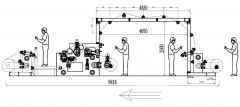 TT-1431 SLOT DIE COATING MACHINE, COATING WIDTH 1600mmTT-1431 SLOT DIE COATING MACHINE, COATING WIDTH 1600mm PARAMETERS 1. COATING METHOD: SLOT DIE COATING 2. MAX. COATING WIDTH: 1600mm 3. COATING WEIGHT: 50 TO 300 GSM 4. UNIFORMITY: ≤10% 5. MECHANICAL SPEED: 1 TO 20 METERS PER MINUTE 6. COATING SPEED: THE COATING SPEED IS DETERMINED ACCORDING TO THE COATING WEIGHT, QUANTITY, ADHESIVE VISCOSITY, THE TEMPERATURE AND THE SUBSTRATE. 7. ROLLER WIDTH: 1750mm (ACTUAL WORKING WIDTH OF PAPER ROLL IS 1600mm) 8. MAX. UNWINDING DIAMETER: 1250mm 9. MAX. REWINDING DIAMETER: 950mm 10. UNWINDING TENSION: ≤600N 11. FILM UNWINDING TENSION: ≤200N 12. WINDING TENSION: ≤600N 13. GLUE MELTING SPEED: 310 KG/HOUR 14. GLUE INPUT HOSE: TEFLON TUBE 15. GLUE MELTING TEMPERATURE: ABOUT 260°C MAXIMUM 16. MECHANICAL POWER: ABOUT 40 KW 17. INSTALLED POWER: ABOUT 110 KW 18. POWER SUPPLY: ABOUT 440 VOLTS, 60Hz 19. AIR SOURCE: 0.6 TO 0.8 MPA 20. WATER SOURCE: 0.15 TO 0.4 MPA CIRCULATING COOLING WATER 21. DIMENSIONS: 9000 (LENGTH) X 6600 (WIDTH) X 2300mm 22. THE AMOUNT OF GLUE AND THE GLUE SPEED ARE TRACKED SYNCHRONOUSLY, AND CAN ALSO BE ADJUSTED INDEPENDENTLY QUANTITY: 1 Learn More
 -
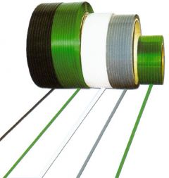 E-4258 POLYESTER PACKING TAPE MACHINE (FROM RECYCLED PET SCRAP)INVENTORY NUMBER: E-4258 POLYESTER PACKING TAPE MACHINE (FROM RECYCLED PET SCRAP): XDC TSE-65/32 PET PRODUCTION CONDITION: NEW 1. ELECTRICAL VOLTAGE: 380V/3P/50HZ OR AS PER CUSTOMER 2. MATERIAL: PET SCRAP 3. MAX. EXTRUSION OUTPUT: 350KG PER HOUR NOTE:PRODUCTION CAPACITY DEPENDS ON RAW MATERIAL AND OPERATION. 4. SPECIFICATION:WIDTH OF TAPE 9 TO 24 mm, THICKNESS: 0.5 TO 1.2 mm 5. LINE SPEED:80M/MIN 6. CENTER HEIGHT OF EXTRUDER: 1000 mm 7. OPERATION DIRECTION: FROM RIGHT TO LEFT 8. POWER REQUIREMENT: 212KW(APPROX. 127KW AT CONTINUOUS USAGE) 9. COOLING RECYCLE: ≤20℃ ≥0.3MPA ~2T/H 10. AIR CONSUMPTION: 0.4 CUBIC METER PER MINUTE; PRESSURE >0.5MPA QUANTITY AVAILABLE: 1 Learn More
 -
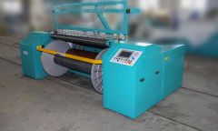 V-2005 WARPER AND CREEL FOR DENIM YARNS WITH 48 BEAMS; 1800mm WIDTH X 1400mm DIAMETERV-2005 WARPER AND CREEL FOR DENIM YARNS WITH 48 BEAMS; 1800mm WIDTH X 1400mm DIAMETER MAXIMUM WARPING SPEED: 1000 METERS PER MINUTE WARP DENSITY: 0.3 TO 0.65 G/cm3; BRAKE SYSTEM: PNEUMATIC-HYDRAULIC CLAMP-BRAKES ON GUIDE ROLLER, WARPING BEAM, PRESS ROLLER; BRAKING DISTANCE: ≤4M (AT SPEED OF 500 METERS PER MINUTE); LENGTH MEASURING: LENGTH MEASURING ON PRESSURE ROLLER WHEN WORKING, LENGTH MEASURING ON WARPING BEAM WHEN PRESS ROLLER BACKWARDS; LENGTH MEASURING ACCURACY: ±0.1%; PRESS METHOD: CYLINDER PUSHES PRESS ROLLER GIVING PARALLEL PRESSURE ALONG THE INCLINED LINEAR GUIDE, PNEUMATIC DISC OFFERS AUXILIARY DAMPING PRESSURE; EXPANSION REED TYPE: W SHAPE, MOVABLE UP AND DOWN, LEFT AND RIGHT; REED TRAVERSE RANGE: 0 TO 40mm ADJUSTABLE; REED TRAVERSE ADJUSTMENT: MANUALLY; REED TRAVERSE FREQUENCY: 24 CYCLES PER MINUTE; EXPANSION REED STRETCH METHOD: ELECTRICAL; REED CENTERING METHOD: ELECTRICAL; BEAM CLAMP: PNEUMATIC; PRESS ROLLER CENTERING: ELECTRICAL; WORKSTATION: TOUCH SCREEN, BUTTONS ON SAFETY BAR. QUANTITY: 1 SET SHIPPING NOTICE: 1 40FT CONTAINER FOR WARPER AND CREEL 1 40FT CONTAINER FOR 48 BEAMS TIME TO BUILD THE MACHINE: 100 DAYS Learn More