Search results for: 'Generator power plant 60'
- Related search terms
- plant
- Generator
- Power pla
- Generator'
- Generator power
-
 J-4722 GE LM6000 PA GAS TURBINE, 42 MW, 50 Hz, DUAL FUEL, 10,500 VOLTSJ-4722 GE LM6000 PA GAS TURBINE, 42 MW, 50 Hz, DUAL FUEL, 10,500 VOLTS MAKE: GE MODEL: LM6000 PA YEAR: 1993 42 MW 50 Hz DUAL FUEL 10,500 VOLTS CONDITION: USED, 12,000 HOURS QUANTITY: 1 Learn More
 -
 TT-7277 ABB UNUSED FUEL GAS COMPRESSOR FOR 2000MW COMBINED POWER PLANT, YEAR 1996, 60HzTT-7277 ABB UNUSED FUEL GAS COMPRESSOR FOR 2000MW COMBINED POWER PLANT, YEAR 1996, 60Hz 1. CONDITION: USED 2. REPORTEDLY UNUSED FUEL GAS COMPRESSOR FOR 2000MW COMBINED POWER PLANT. 3. BRAND: ABB POWER GENERATOR 4. MANUFACTURING YEAR: 1996 5. CAPACITY FOR 1300MW GAS TURBINE (2000MW COMBINED CYCLE POWER PLANT) QUANTITY: 1 Learn More
 -
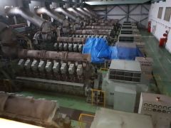
 TT-6408 WARTSILA POWER PLANT, 28MW, YEAR 2001, 60HzTT-6408 WARTSILA POWER PLANT, 28MW, YEAR 2001, 60Hz 1. WARTSILA POWER PLANT 2. WARTSILA W18V32 DIESEL ENGINE GENERATORS 3. IDEAL FOR LARGE-SCALE ELECTRICITY PRODUCTION 4. THIS PLANT HAS BEEN PRESERVED AND IS READY FOR IMMEDIATE INSPECTION AND DELIVERY. Learn More
 -
 TT-1904 HFO WARTSILA W18V32 POWER PLANT, 7MW, 60Hz, YEAR 2001TT-1904 HFO WARTSILA W18V32 POWER PLANT, 7MW, 60Hz, YEAR 2001 MAIN SPECIFICATIONS: ENGINE MODEL: W18V32 MAKER: WARTSILA CONTINUOUS OUTPUT: 7,050KWE X 720 RPM FREQUENCY & VOLTAGE: 60Hz & 13,800V YEAR OF PRODUCTION: 2001 FUEL OIL: DIESEL OIL PLANT AUXILIARY EQUIPMENT: 1 SET RUNNING HOURS: ABOUT 35,000 HOURS STATUS: DISMANTLED IN 2018 AND PRESERVED INSPECTION: IMMEDIATELY DELIVERY: IMMEDIATELY AFTER SIGNING CONTRACT QUANTITY: 5 Learn More
 -
 TT-5649 STEAM TURBINE POWER PLANT, 147MW, 60Hz, YEAR 1999TT-5649 STEAM TURBINE POWER PLANT, 147MW, 60Hz, YEAR 1999 STEAM TURBINE POWER PLANT BRAND: MITSUBISHI (JAPAN) MANUFACTURING YEAR: 1999 RUNNING HOUR: 43,970 HOURS OUTPUT: 147MW (AT GENERATOR TERMINAL) Learn More
 -
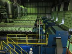
 TT-1882 HFO MITSUBISHI 18KU30A POWER PLANT, 45MW 50Hz, 5.6MW, YEAR 1998TT-1882 HFO MITSUBISHI 18KU30A POWER PLANT, 45MW 50Hz, 5.6MW, YEAR 1998 MAIN SPECIFICATIONS: ENGINE MODEL: 18KU30A BRAND: MITSUBISHI CONTINUOUS OUTPUT: 5,600KWE X 750 RPM FREQUENCY & VOLTAGE: 50HZ & 11,000V YEAR OF PRODUCTION: 1998 FUEL OIL: HFO / DO PLANT AUXILIARY EQUIPMENT: 1 SET RUNNING HOURS: ABT. 21,000 HOURS QUANTITY: 8 Learn More
 -
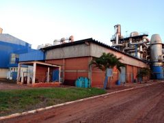 SUGAR AND ALCOHOL PLANTREFERENCE NUMBER: A-2511 SUGAR AND ALCOHOL PLANT CANE UNLOAD SECTOR THE CANE UNLOADING SECTOR IS EQUIPPED WITH THE EQUIPMENT LISTED BELOW IN THE CONDITION TO CARRY OUT A GRINDING OF 8400 TCD WHICH CORRESPONDS TO A HARVEST OF 1800000 TONNES OF CANE / YEAR • 01 HILO UNLOADER OF STORAGE • 01 HILO UNLOADER OF MILLING • 01 FEEDER SUGARCANE TABLE WITH INCLINATION OF 25 INCHES • 01 FEEDER SUGARCANE TABLE WITH INCLINATION OF 45 INCHES • 02 CRANES WITH CAPACITY OF 20 TONNES • 01 TRANSPORTER TYPE CUSCH - CUSH OF 40 INCHES • 02 MOTOR PUMP WITH CAPACITY OF 1000 M³/H TO 50 MCW FOR CANE WASHING • 01 CONTAMINATED FLUID TREATMENT SYSTEM • 01 METAL STRUCTURE BUILDING MEASURING 20000 X 100000 mm CANE PREPARATION SECTOR THE SUGARCANE PREPARATION SECTOR IS EQUIPPED WITH THE FOLLOWING AUTOMATED EQUIPMENT WITH THE CONTROL BY THE SUPERVISORY INSTALLED IN THE CONTROL ROOM AS SHOWN BELOW TO PERFORM A CRUSHING OF 7200 TCD WHICH CORRESPONDS TO A CROP OF 1600000 TONS OF SUGARCANE / YEAR • 01 METALLIC CONVEYOR OF 60 INCHES • 01 LEVELING OF CANE OF 60 INCHES • 01 CANE KNIVES SET TYPE COP-8 OF 60 INCHES • 01 CAN SHREDDER SET TYPE COP-5 OF 60 INCHES • 01 FEEDER ROLL 60 IINCHES • 01 RUBBER TRANSPORTER FOR CANE SHREDDED OF 60 INCHES • 01 TGM TURBINE FOR KNIVES SET • 01 TGM TURBINE FOR SHREDDER SET • 01 HIGH AND LOWER SPEED REDUCER OF KNIVES SET • 01 HIGH AND LOWER SPEED REDUCER OF SHREDDER SET • 01 REDUCER FOR METALLIC CONVEYOR • 01 REDUCER FOR FEEDER ROLL • 01 REDUCER OF SHREDDED CANE TRANSPORTER TYPE BELT MILLING CANE SECTOR THE CANE MILLING SECTOR OF THE PLANT IS EQUIPPED WITH THE FOLLOWING AUTOMATED EQUIPMENT WITH THE CONTROL BY THE SUPERVISORY INSTALLED IN THE CONTROL ROOM TO CARRY OUT A GRINDING OF 7200 TCD CORRESPONDING TO A 222 - DAY HARVEST TO GRIND 1600000 TONS. CANE / YEAR • 04 MILLS OF 32 X 60 INCHES • 03 INTERMIDIATE TRANSPORTER OF 60 INCHES • 01 ROTARY SIEVE FOR MILLING 300 TCD • 01 TGM TURBINE OF DRIVING THE 1º / 2º MILLS • 01 TGM TURBINE OF DRIVING OF 3º / 4º MILLS • 01 REDUCER OF HIGH AND LOW SPEED OF DRIVING THE 1º / 2º MILLS • 01 REDUCER OF HIGH AND LOW SPEED OF DRIVING THE 3º / 4º MILLS • 03 REDUCER INTERMEDIATE TRANSPORTER OF 60 INCHES • 02 PUMPS OF 1ST JUICE • 02 PUMPS OF JUICE IMBIBITION OF 3RD FOR 2ND MILL • 02 PUMPS OF JUICE IMBIBITION OF 4TH FOR 3RD MILLS • 02 PUMPS OF MIXED JUICE OF MILL FOR JUICE TREATMENT STEAM GENERATION SECTOR THE STEAM GENERATION SECTOR OF THE PLANT IS PREPARED TODAY TO PERFORM A 7200 TCD GRINDING CORRESPONDING TO A 220 - DAY HARVEST TO GRIND 1600000 TON. CANE / YEAR WITH THE FOLLOWING AUTOMATED EQUIPMENT WITH CONTROL BY THE SUPERVISORY INSTALLED IN THE CONTROL ROOM AS SHOWN BELOW • 01 BOILER N ° 01, MODEL: TS-3-150 MODIFIED FOR CBS-120-21 KG / CM² TODAY GENERATES AN AVERAGE OF 11000 KG / HR OF STEAM AT A PRESSURE OF 21 KG / CM² • 01 BOILER N ° 02, MODEL: TS-3-150-21 KG / CM² TODAY GENERATES AN AVERAGE OF 55000 KG / HR OF STEAM AT A PRESSURE OF 21 KG / CM² • 01 DEAERATOR WITH A CAPACITY OF 70 M³ • 01 78 INCHES BAGASSE METALLIC TRANSPORTER OF 32000 mm LENGTH • 01 48 INCHES BAGASSE TRANSPORTER FROM MILL TO BOILER • 01 48 INCHES BAGASSE RETURN TRANSPORTER FOR BOILER • 01 REDUCER OF BAGASSE TRANSPORTER FROM MILL TOBOILER • 01 REDUCER OF BAGASSE RETURN TRANSPORTER TOBOILER • 02 MOTO - PUMPS OF WATER FEEDING OF DEAERATOR • 02 MOTO - PUMPS OF WATER TREATMENT OF BOILER • 01 MOTO - PUMP WITH CAPACITY OF 300 M³/H TO 350 MCW FOR WATER FEEDING OF BOILER • 01 TURBO-PUMP WITH CAPACITY OF 300 M³/H TO 350 MCW FOR WATER FEEDING OF BOILER • 02 MOTO-PUMPS WITH CAPACITY OF 220 M³/H TO 50 MCW FOR WET SCRUBBER OF BOILER NO. 2 • 03 MOTO - PUMPS OF 40 M³/H TO 300 MCW • 01 METALLIC RESERVOIR WITH 200 M³ OF CONDENSED WATER CAPACITY POWER GENERATION SECTOR THE POWER GENERATION SECTOR IS EQUIPPED WITH THE FOLLOWING MODERN AND AUTOMATED EQUIPMENT LISTED BELOW TO MEET A GRINDING OF 8400 TCD • 01 THREE - PHASE GENERATOR OF 6250 KVA – 13800 VOLTS – 60Hz • 01 TGM STEAM TURBINE MODEL TM - 5000 • 01 REDUCER RENK - ZANINI WITH CAPACITY OF 5000 KW • SEVERAL ELECTRICALS PANELS OF THE GENERATOR • 01 TURBO GENERATOR HOUSE BUILDING • 02 WATER COOLING TOWERS FOR THE TURBO-GENERATOR • 02 MOTO - PUMPS OF 100 M³/H TO 30 MCW SUGAR FACTORY THE SUGAR FACTORY WAS SET UP BETWEEN 2007 / 2008 AND COMPLETELY AUTOMATED WITH THE CONTROL BY THE SUPERVISORY INSTALLED IN THE CONTROL ROOM, PRODUCING AN AVERAGE OF 500000 KG OF VHP SUGAR PER DAY, A VALUE CORRESPONDING TO A MILLING OF 5000 TCD. THE TRANSPORT OF THIS SUGAR MANUFACTURED AT THE DECASA PLANT IS BEING TRANSPORTED BY MEANS OF A BUCKET VEHICLE WITH A DESTINATION INFORMED BY THE CUSTOMER. FOR THIS PLANT TO PRODUCE CRYSTAL SUGAR IC - 150, WE WILL NEED TO ACQUIRE AND ASSEMBLE THE FOLLOWING EQUIPMENT • SULFITATION EQUIPAMENT • BAGGING EQUIPMENT OF 50 KG BAGS • BUILD OR RENT AN INFLATABLE WAREHOUSE TO STORE SUGAR WITH THE INSTALLATION OF THIS EQUIPMENT, THE SUGAR FACTORY IS PREPARED TO RECEIVE A MILLING OF 5000 TCD CORRESPONDING TO A DAILY PRODUCTION OF 500000 KG OF CRYSTAL SUGAR IC - 150 PER DAY ALCOHOL DISTILLERY THE DISTILLERY WAS INSTALLED IN 1982 WITH A CAPACITY OF 300000 LITERS OF HYDRATED ALCOHOL PER DAY. WHEN THE FORMER OWNER'S UNIT WAS SOLD TO THE OLIVAL TENÓRIO GROUP IN 2003, THE NEW ENTREPRENEUR INVESTED IN THE MANUFACTURE OF ALCOHOL IN 2006 BY INSTALLING ANOTHER COLUMN OF DISTILLATION WITH A CAPACITY OF 300,000 LITERS AND AUTOMATED 100% INCREASING ITS PRODUCTION CAPACITY TO 600,000 LITERS OF HYDRATED ALCOHOL PER DAY • 02 TYPE “A” DISTILLATION COLUMNS WITH CAPACITY TO PRODUCE 300 M³ OF ALCOHOL / DAY • 02 TYPE “B” RECTIFICATION COLUMNS WITH CAPACITY FOR PRODUCTION OF 300 M³ OF ALCOHOL / DAY • 01 TYPE “A” DISTILLATION COLUMN WITH CAPACITY FOR PRODUCTION OF 300 M³ OF ALCOHOL / DAY • 01 TYPE “B” RECTIFICATION COLUMN WITH CAPACITY FOR PRODUCTION OF 300 M³ OF ALCOHOL / DAY • 09 TUBULAR HEAT EXCHANGERS TYPE “K” • 02 TUBULAR HEAT EXCHANGERS TYPE “J” • 02 TUBULAR HEAT EXCHANGERS TYPE “E” • 02 TUBULAR HEAT EXCHANGERS TYPE “E1” • 02 TUBULAR HEAT EXCHANGERS TYPE “E2” • 02 TUBULAR HEAT EXCHANGERS TYPE “R” • 02 TUBULAR HEAT EXCHANGERS TYPE “R1” • 11 NEW FERMENTATION VATS WITH A CAPACITY OF 300 M³ • 03 PLATE HEAT EXCHANGERS FOR THE WORT • 05 PLATE TYPE HEAT EXCHANGERS FOR VATS • 01 VAT FOR WINE • 01 CO₂ RECOVERY COLUMN • 02 PUMPS WITH A CAPACITY OF 600 M³ / H - 50 MCA FOR THE COOLING SYSTEM OF THE PLATE HEAT EXCHANGERS • 01 PUMP WITH A CAPACITY OF 800 M³ / H FOR THE COOLING SYSTEM OF THE PLATE HEAT EXCHANGERS • 02 CENTRÍFUGES HAD - 90 • 04 CENTRÍFUGES HAD - 60 WITH THE INSTALLATION OF THIS EQUIPMENT, THE ALCOHOL DISTILLERY IS PREPARED TO PRODUCE 600000 LITERS OF ALCOHOL PER DAY, RECEIVING A MILLING OF 6500 TCD CORRESPONDING TO 2500000 TONS OF CANE / YEAR Learn More
 -
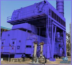
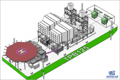 TT-3411 REVERSE OSMOSIS PLANT, PRODUCTION 20 MILLION US GALLONS PER DAY – SEA WATER DESALINATION PLANTTT-3411 REVERSE OSMOSIS PLANT, PRODUCTION 20 MILLION US GALLONS PER DAY – SEA WATER DESALINATION PLANT 173 MWE POWER BARGE SGT SERIES 5 2000E TURBINE AMOUNTED ON BARGE BRAND NEW UNIT TWIN INSTALLATION. 300MW 2856 RPM 60Hz - CAN OPERATE ON EITHER LIQUID FUEL OR GAS; - TRANSPORTABLE BY TOWING OR ON HEAVY LIFT VESSELS; - CAN BE MOORED AT BERTH OR POSITIONED IN PROTECTED WATERS USING SPUDS; - FUEL SUPPLY BY STORAGE BARGE OR PIPED FROM LAND-BASED STORAGE; - ENVIRONMENTALLY FRIENDLY; - BARGE & SYSTEMS ABS CLASSED; - APPROVED BY LLOYDS OF LONDON. Learn More
 -
 G-0784 RIETER FDY EXTRUSION EQUIPMENT FOR POLYPROPYLENE YEAR 1996/98
REFERENCE NUMBER: G-0784
RIETER FDY EXTRUSION EQUIPMENT FOR POLYPROPYLENE YEAR 1996/98
1. Machine m26/39:
Year 1996
For 1 fdy spinning line with 2+4 positions, each position with 4 ends
Product: fdy-yarn on bobbins
Raw material: pp, dried filament grade chips
Yarn count range: 150 – 400 dtex
Winder speed for target: 4000 m/min
Machine technical data:
Position gauge: 800 mm
Spinning pump capacity: 4x10 ccm/rev
Spinneret size diameter: 95 mm
Quench width: 670 mm
Quench length: 1700 mm
Number of spin-finish pumps per position: 1
Capacity of spin-finish pump: 4x0.05 ccm/rev
Number of winders/position: 1
Type of winder: riemat a6-094
Number of packages/winder: 4
Maximum package diameter: 420 mm
Package stroke: 190 mm
Package weight at 280 mm package diameter: approx. 6.2 kg
Detailed technical specifications:
Extruder for 4 positions Year 1998:
1 extruder type e1. 105-30m:
-nominal extruder capacity: max 275 kg/h for pp
-operational extruder capacity: max 248 kg/h for pp
-screw diameter: 105 mm
-l/d ratio: 30
-barrel with:
electrical ceramic heaters
7 heating zones, each zone equipped with one 2xpt100
heating zone capacity approx. 58 kw
inlet zone, water cooled
nozzle for nitrogen purge
insulation
-screw with torpedo mixing head
-reduction gear, including belt transmission to motor
-dc motor, rated power approx. 95kw
-extruder frame
1 extruder measuring head, dowtherm vapour heated
-measuring head comprising:
coarse filter
insulation
-double pt100, one each for melt and dowtherm vapour temperature
-pressure sensors for melt pressure, one in front and one behind the coarse filter
1 melt distribution system, dowtherm vapour heated
-melt distribution system comprising
main product pipe between extruder, measuring head and melt distributor.
Extruder for 2 positions Year 1998:
1 extruder type e1. 60-30
-nominal extruder capacity: max 275 kg/h for pp
-operational extruder capacity: max 248 kg/h for pp
-screw diameter: 60 mm
-l/d ratio: 30
-barrel with
electrical ceramic heaters
6 heating zones, each zone equipped with one 2xpt100
heating zone capacity approx. 17 kw
inlet zone, water cooled
insulation
-screw nitrited with maddock mixing head
-reduction gear, including belt transmission to motor
-dc motor, rated power approx. 22kw
-extruder frame
1 extruder measuring head, electrically heated year 1998
-measuring head comprising:
insulation
Double pt100, one each for melt and dowtherm vapour temperature
pressure sensors for melt pressure
burst disc for power switch-off at overpressure.
1 melt distribution system, dowtherm vapour heated
-melt distribution system comprising
main product pipe between extruder, measuring head and melt distributor.
1 riebeam bottom loading spinning beam year 1998
-beam comprising:
welded-in pump blocks with bolted pump adapter plate
silumin insulation blocks
melt distribution pipes with polished inner surfaces
efficient vapour heating on all sides of spin pumps
optimized heat condustion to the spinnerets
1 freezing valve upstream of each spinpump
2 pressure sensors for measuring the melt pressure in front and behind the spinpump
(2 per line)
heating box, completely insulated
heating by dowtherm vapour
1 double pt100 for measuring and controlling the heating box temperature
Designed as follows:
-bottom loading of rieter quickfit spinpacks
-design temperature 320°c
-maximum allowable working pressure: 300 bar for melt pipe and 2.57 bar for jacket
Dowtherm evaporator and components for heating system:
-electrically heated, total capacity approx 25 kw
-shut-off valves
-drainage valves
-dry protection sensor
-magnetic controlled level gauge
- vent system on top of measuring head.
Poy spin packs, type rieter quickfit:
-max pressure in the spinpack: 350 bar
-design temperature: 320 °c
-spinneret outside dimensions: 95 mm
-bottom loading design
-bayonet locking, insert and tighten by turning 90°
-self sealing system
-sand or metal powder filtration, 3 cm filling depth
-wire mesh filters
Spin pumps with motors and gears:
Gear pumps, 4-fold
Capacity 4 x 6 ccm/rev
Each spin pump system comprising
Individual drive motor with flange connection to the reduction gear
Hollow gear shaft for installation of spin pump shaft
Shaft with shear pin protection
Reduction ratio 1:80
Pump speed: 8-30 rev/min
Motor type: synchronous ac-motor
Rated power: 500w at 50 cps
Quench air cabinets bsk 670/1700:
Each cabinet comprising:
-rigid cabinet made from welded sheet metal, painted, side walls made from alu sheet metal
-air rectifier consisting of different layers of perforated metal sheets, rectifiers removable to the front for cleaning.
-1 perforated hinged door
-air inlet duct flanged with counter flange, comprising air flow regulating flaps
-interfloor filament duct, length 2000 mm
-alu chutes for start-up
-nozzles for connection of differential pressure gauge.
Spinning vapour exhausts:
-exhaust hood per spinning position for removal of spinning vapour
-hood designed as follows:
made from stainless steel
air flow regulation flap
hood removable for cleaning
Take-up frames, type riedraw 1:
Welded steel frame, housing all drawrolls, compressed air supply pipes for the aspirator units and the yarn waste pipes within the fdy take-up unit.
Per position:
4 inlet yarn guides
4 spin finish application nozzles
1 yarn cutter / aspirator unit
1 spin finish pump
4 centring yarn guides
4 intermingling units
rolls as described further
1 automatic winder riemat a6-094
Drawrolls year 1998:
Mono 1 with 1 rievap 32 dual shell drawroll, type j7/32-40, ot40
Speed range: 750 to 4000 mpm
Roll diameter: 190 mm
Working width: 250 mm
Temperature range: 45-250°c
And 1 bearing separator roll, type srd60 hard chromium plated
Duo 1 with 2 rievap 32 dual shell drawroll, type j7/32-60, ot40
Speedrange: 1000 to 6000 mpm
Roll diameter: 190 mm
Working width: 250 mm
Temperature range: 45-250°c
Duo 2 with 2 rievap 32 dual shell drawroll, type j7/32-60, ot40
Speedrange: 1000 to 6000 mpm
Roll diameter: 190 mm
Working width: 250 mm
Temperature range: 45-250°c
Duo 3 with 2 cold draw roll units each type j7/45-55
Speedrange: 1800 to 5500 mpm
Roll diameter: 150 mm
Working width: 180 mm
Automatic and wasteless winder riemat a6-094
Spindle driven
Number of ends per winder: 4 ends
Yarn count range: 15 to 1000 dtex
Take up speed: 2500 to 5500 m/min
Chuck length: 900 mm
190 mm stroke, 420 mm outside package diameter
Package volume: 24.7 dm³
Tube bore: 94 ±0.2 mm
Tube outside diameter: 106 ±0.4 mm
Tube length: 225 ±0.5 mm
Oil-mist lubrication unit:
Compressed air distribution station
Mobile aspirator guns with hoses
Electrical control equipment
-for electrical power
general: 3 x 380v/50hz plus ground wire
euro-standard: 3x400v 50 or 60hz plus ground wire
maximum voltage variation ±10% measured at terminals of cabinets
maximum frequency variation: ±2%
Process control system (cif):
fully integrated control system to control and monitor the entire spinning line.
the central monitoring unit si linked to the plc of the spinning section and the plcs of each spinning position.
Drive and heater control year 1998:
Spinning section:
Speed adjustment for the extruder motor is done via a dc-convertor
To achieve a constant pressure at the extruder outlet, the output of the pressure controller is transmitted to the dc-converter to adjust the extruder speed.
The feedback of the actual extruder speed is done by a tacho generator mounted on the extruder motor.
One common frequency inverter supplies the synchronous ac motors for the spin pumps.
According to process conditions, the plc transmits the setpoint to the inverter.
All motors are equipped with an overload protection.
Solid state relays heat each extruder zone and spinning beam.
Each extruder zone and the spinning beam represent an independent control loop.
Take-up section:
The inverter unit is a processor-controlled static frequency inverter for powering the 3-phase motors.
All inverter units in a position cabinet are supplied with approx 570v dc from a common rectifier.
Heating system:
The heating unit rhu is processor-controlled.
The power supply is taken straight from 3-phase 380/400v which powers the cabinet.
The inductor is fitted inside the draw roll.
The rhu switches the current on and off in this inductor. While current flows, a voltage is inducted into the
Rotating draw roll.
This sets up a short-circuit current in the draw roll, thereby heating the roll unit.
2. Machines m27/ 28 / 30 year 1998:
For 3 fdy spinning lines each with 2 positions, and each position with 4 ends
Product: fdy-yarn on bobbins
Raw material: pp, dried filament grade chips
Yarn count range: 150 – 400 dtex
Winder speed for target: 4000 m/min
Machine technical data:
Position gauge: 1000 mm
Spinning pump capacity: 4x7.5 ccm/rev
Spinneret size diameter: 95 mm
Quench width: 470 mm
Quench length: 1200 mm
Number of spin-finish pumps per position: 2
Capacity of spin-finish pump: 4x0.16 ccm/rev + 4x0,05 ccm/rev
Number of winders/position: 1
Type of winder: riemat a6-094
Number of packages/winder: 4
Maximum package diameter: 420 mm
Package stroke: 190 mm
Package weight at 280 mm package diameter: approx. 6.2 kg
Detailed technical specifications:
1 extruder type e1. 60-30m
-nominal extruder capacity: max 80 kg/h for pp
-screw diameter: 65 mm
-l/d ratio: 30
-barrel with:
electrical ceramic heaters
7 heating zones, each zone equipped with one 2xpt100
heating zone capacity approx. 22 kw
inlet zone, water cooled
nozzle for nitrogen purge
insulation
-screw with torpedo mixing head
-reduction gear, including belt transmission to motor
-dc motor, rated power approx. 22kw
-extruder frame
1 extruder measuring head, electrically heated:
-measuring head comprising:
coarse filter
insulation
-double pt100, one each for melt and dowtherm vapour temperature
-pressure sensors for melt pressure, one in front and one behind the coarse filter
1 melt distribution system, dowtherm vapour heated:
Melt distribution system comprising:
main product pipe between extruder, measuring head and melt distributor.
1 riebeam bottom loading spinning beam:
-beam comprising:
welded-in pump blocks with bolted pump adapter plate
silumin insulation blocks
melt distribution pipes with polished inner surfaces
efficient vapour heating on all sides of spin pumps
optimized heat condustion to the spinnerets
1 freezing valve upstream of each spinpump
2 pressure sensors for measuring the melt pressure in front and behind the spinpump
(2 per line)
heating box, completely insulated
heating by dowtherm vapour
1 double pt100 for measuring and controlling the heating box temperature
Designed as follows:
-bottom loading of rieter quickfit spinpacks
-design temperature 320°c
-maximum allowable working pressure: 300 bar for melt pipe and 2.57 bar for jacket
Dowtherm evaporator and components for heating system:
-electrically heated, total capacity approx 18 kw
-shut-off valves
-drainage valves
-dry protection sensor
-magnetic controlled
-level gauge
-vent system on top of measuring head.
Poy spin packs, type rieter quickfit:
Max pressure in the spinpack: 350 bar
Design temperature: 320 °c
Spinneret outside dimensions: 95 mm
Bottom loading design
Bayonet locking, insert and tighten by turning 90°
Self sealing system
Sand or metal powder filtration, 3 cm filling depth
Wire mesh filters
Spin pumps with motors and gears:
Gear pumps, 4-fold
Capacity 4 x 7.5 ccm/rev
Each spin pump system comprising
individual drive motor with flange connection to the reduction gear
hollow gear shaft for installation of spin pump shaft
shaft with shear pin protection
reduction ratio: 1:80
pump speed: 8-30 rev/min
motor type: synchronous ac-motor
rated power: 500w at 50 cps
Quench air cabinets bsk 470/1200
Each cabinet comprising:
-rigid cabinet made from welded sheet metal, painted, side walls made from alu sheet metal
-air rectifier consisting of different layers of perforated metal sheets, rectifiers removable to the front for cleaning.
-1 perforated hinged door
-air inlet duct flanged with counter flange, comprising air flow regulating flaps
-interfloor filament duct, length 2000 mm
-alu chutes for start-up
-nozzles for connection of differential pressure gauge.
Spinning vapour exhausts:
-exhaust hood per spinning position for removal of spinning vapour
-hood designed as follows:
made from stainless steel
air flow regulation flap
hood removable for cleaning
Take-up frames, type riedraw 1:
Welded steel frame, housing all drawrolls, compressed air supply pipes for the aspirator units and the yarn waste pipes within the fdy take-up unit.
Per position:
4 inlet yarn guides
2 spin finish application nozzles per end
1 yarn cutter / aspirator unit
2 spin finish pump
4 centring yarn guides
4 pre-intermingling jets
4 intermingling units
1 additional operator panel between duo1 and duo 2.
rolls as described further
1 automatic winder riemat a6-094
Drawrolls:
Mono 1 with 1 rievap 32 dual shell drawroll, type j7/32-40, ot40
Speedrange: 750 to 4000 mpm
Roll diameter: 190 mm
Working width: 250 mm
Temperature range: 45-250°c
And 1 bearing separator roll, type srd60
Hard chromium plated
Duo 1 with 2 rievap 32 dual shell drawroll, type j7/32-60, ot40
Speedrange: 1000 to 6000 mpm
Roll diameter: 190 mm
Working width: 250 mm
Temperature range: 45-250°c
Duo 2 with 2 rievap 32 dual shell drawroll, type j7/32-60, ot40
Speedrange: 1000 to 6000 mpm
Roll diameter: 190 mm
Working width: 250 mm
Temperature range: 45-250°c
Duo 3 with 2 cold draw roll units each type j7/45-55
Speedrange: 1800 to 5500 mpm
Roll diameter: 150 mm
Working width: 180 mm
Automatic and wasteless winder riemat a6-094:
Spindle driven
Number of ends per winder: 4 ends
Yarn count range: 15 to 1000 dtex
Take up speed: 2500 to 5500 m/min
Chuck length: 900 mm
190 mm stroke, 420 mm outside package diameter
Package volume: 24.7 dm³
Tube bore: 94 ± 0.2 mm
Tube outside diameter: 106 ± 0.4 mm
Tube length: 225 ± 0.5 mm
Compressed air distribution station:
Mobile aspirator guns with hoses
Electrical control equipment
For electrical power
general : 3 x 380v/50hz plus ground wire
Euro-standard: 3x400v 50 or 60hz plus ground wire
Maximum voltage variation ±10% measured at terminals of cabinets
maximum frequency variation: ±2%
Process control system (cif):
Fully integrated control system to control and monitor the entire spinning line.
The central monitoring unit si linked to the plc of the spinning section and the plcs of each spinning position.
Drive and heater control:
Spinning section.
Speed adjustment for the extruder motor is done via a dc-convertor.
To achieve a constant pressure at the extruder outlet, the output of the pressure controller is transmitted to the dc-converter to adjust the extruder speed.
The feedback of the actual extruder speed is done by a tacho generator mounted on the extruder motor.
One common frequency inverter supplies the synchronous ac motors for the spin pumps.
According to process conditions, the plc transmits the setpoint to the inverter.
All motors are equipped with an overload protection.
Solid state relays heat each extruder zone and spinning beam.
Each extruder zone and the spinning beam represent an independent control loop.
Take-up section:
The inverter unit is a processor-controlled static frequency inverter for powering the 3-phase motors.
All inverter units in a position cabinet are supplied with approx 570v dc from a common rectifier.
Heating system:
The heating unit rhu is processor-controlled.
The power supply is taken straight from 3-phase 380/400v which powers the cabinet.
The inductor is fitted inside the draw roll.
The rhu switches the current on and off in this inductor.
While current flows, a voltage is inducted into the rotating draw roll.
This sets up a short-circuit current in the draw roll, thereby heating the roll unit.
HOURLY PRODUCTION:
FOR 150 DENIER @ 3500 MPM WINDER SPEED, THE HOURLY PRODUCTION IS 3.5 KG/BOBBIN.
AS THERE IS 4 ENDS PER POSITION, THIS MEANS 14 KG/HOUR/POSITION
M26/39 ARE OF 2 + 4 POSITIONS; HENCE M26 = 28 KG/HOUR AND M39 = 56 KG/HOUR
M27/28/30 ARE OF 2 POSITIONS EACH, HENCE 28 KG/HOUR EACH.
(AS PER OUR PEOPLE AT THE EXTRUSION PLANT, THEY WERE RUNNING TRIALS TO PRODUCE THE 150 DENIER @ 4000 MPM WINDER SPEED)
FOR 300 DENIER @ 3600 MPM WINDER SPEED, THE HOURLY PRODUCTION IS 7.2 KG/BOBBIN.
AS THERE IS 4 ENDS PER POSITION, THIS MEANS 28.8 KG/HOUR/POSITION
M26/39 ARE OF 2 + 4 POSITIONS; HENCE M26 = 57.6 KG/HOUR AND M39 = 115.2 KG/HOUR
M27/28/30 ARE OF 2 POSITIONS EACH, HENCE 57.6 KG/HOUR EACH.
FOR 600 DENIER @ 2200 MPM WINDER SPEED, (SPEED LIMITATION DUE TO EXTRUDER CAPACITY) THE HOURLY PRODUCTION IS 8.8 KG/BOBBIN.
AS THERE IS 4 ENDS PER POSITION, THIS MEANS 35.2 KG/HOUR/POSITION
M26/39 ARE OF 2 + 4 POSITIONS; HENCE M26 = 70.4 KG/HOUR AND M39 = 140.8 KG/HOUR
M27/28/30 ARE OF 2 POSITIONS EACH, HENCE 70.4 KG/HOUR EACH.
MACHINE HAS BEEN PARTIALLY DISASSEMBLED (EXTRUDERS AND SPINBEAMS HAVE BEEN TAKEN DOWN TO GROUNDFLOOR) REST OF THE EQUIPMENT STILL TO BE DISASSEMBLED
Learn More -
 TT-8039 SIEMENS SST-400 30MW STEAM TURBINE+38MW GENERATOR FOR POWER PLANT, YEAR 2011TT-8039 SIEMENS SST-400 30MW STEAM TURBINE+38MW GENERATOR FOR POWER PLANT, YEAR 2011 1. SIEMENS SST-400 30MW STEAM TURBINE+38MW GENERATOR FOR POWER PLANT 2. BRAND: SIEMENS 3. MODEL: SST400 4. TYPE: STEAM TURBINES 5. CONDITION: NEW QUANTITY: 1 Learn More